Configuration menu details, Configuration menu details -7 – Verilink DIU 2130 (880-503297-001) Product Manual User Manual
Page 31
DIU 2130 Configuration
Verilink
3-7
Within 15 seconds of connecting the T1 circuit, the NET LED on the
front of the controller module should change from red to green. If
it does not, the Diagnostics Menu of the controller module may be
used for troubleshooting.
Configuration Menu Details
The lowercase p shown in some prompts is a variable representing
the port number. Use the number 1 or the number 2 in place of the
p, depending on which port you want to configure.
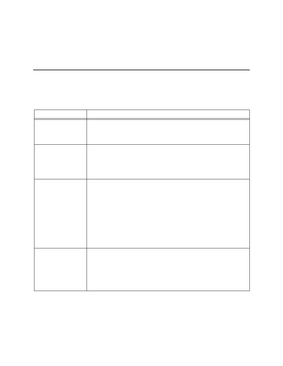
Table 3-3
Configuration Menu Commands
Command
Options
Save Configuration
If a DIU 2130 is controlled through an NCC, the
Save Configuration
option
saves the DIU configuration to battery-protected NVRAM in the NCC module.
If the DIU 2130 is controlled by an SCC, the Save Configuration option will
return an error message. This function is not supported by the SCC.
Restore Config
If a DIU 2130 is controlled through an NCC, the
Restore Configuration
restores the original DIU configuration from the battery-protected NVRAM in the
NCC. This works only if the configuration of the DIU has been previously saved
to the NCC.
If the DIU 2130 is controlled by an SCC, the Restore CSU Configuration option
will return an error message. This function is not supported by the SCC.
CSU
The
C
command is used to assign the DIU 2130 to the CSU from which and to
which it will be transferring user data. The selected CSU is then displayed inside
brackets. The DIU 2130 will poll the CSU to get information such as which of
the data busses in the shelf is to be used (A, B or C).
During DIU 2130 installation, assign the CSU first.
New DIU 2130s are shipped with a value of 0,0 for this option. Since there is no
slot 0, shelf 0, this has the effect of insuring that the DIU 2130 may be added to
a shelf with operating circuits and not bring down any existing applications.
If you fail to change the CSU assignment from 0,0 to the desired value, the DCD
lead to the DTE will remain in “low” (inactive) state and the card will appear to
be defective.
Timing Source
The
T
command on the
DIU 2130 Configuration/Diagnostics
menu is
used to set the master timing source for the DIU 2130. The submenu looks like:
T1 timing source (1) port 1 (2) port 2 (3) csu >
In most cases, the value CSU will be selected to let the timing source being used
by the associated CSU also time the DIU 2130. In the less common case of tail
circuit timing, where a dataport is being connected via a crossover cable to
another DCE, a dataport may be selected as the input source for timing.