Internal timing, External timing, Internal timing -6 external timing -6 – Verilink DIU 2130 (880-503297-001) Product Manual User Manual
Page 86
DIU/DIM Details
7-6
Verilink
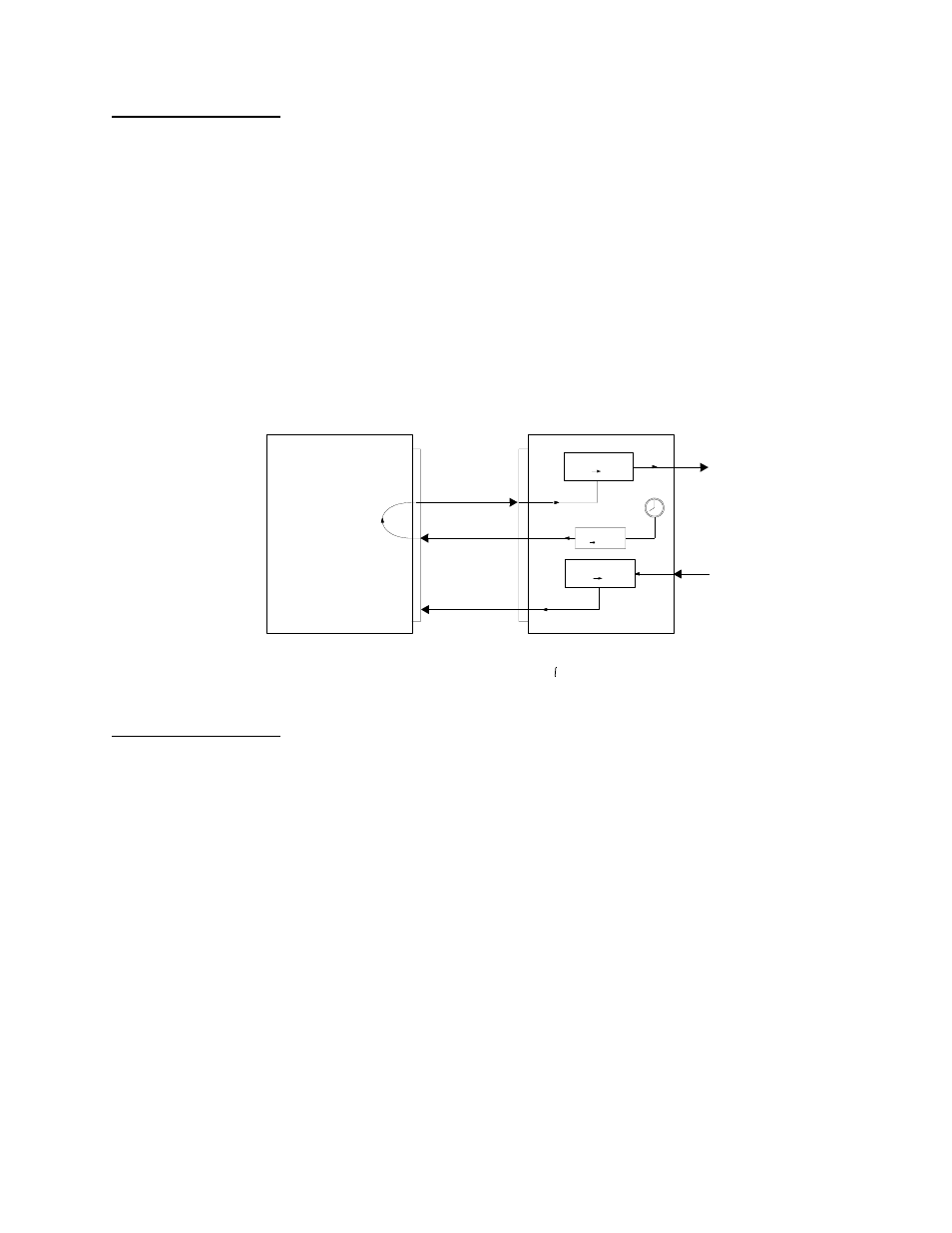
Internal Timing
In internal timing, the ST signal is generated from an internal
oscillator, while the RT signal is generated from the recovered T1
signal clock. There is no connection between the two transmission
directions; RT is generated separately from ST, and the T1 transmit
frequency is not necessarily synchronized with the T1 receive
frequency.
The T1 transmit and receive frequencies will be synchronized, if
the far-end circuit is looped-timed. However, the T1 transmit and
receive frequencies will be different if the far-end DIU is set for
internal or external timing.
Figure 7-10 shows the timing signal paths for internal timing.
Figure 7-10 Internal Timing
External Timing
In external timing, the ST signal is generated from an external
oscillator, while the RT signal is generated from the recovered T1
signal clock. There is no connection between the two transmission
directions; RT is generated separately from ST, and the T1 transmit
frequency is not necessarily synchronized with the T1 receive
frequency.
The T1 transmit and receive frequencies will be synchronized, if
the far-end circuit is looped-timed. However, the T1 transmit and
receive frequencies will be different if the far-end DIU is set for
internal or external timing. SeeFigure 7-11.
Input Buffer
f
I
f
h
Freq Conv
f
h
f
l
Clock Recovery
f
h
f
l
Customer
Equipment
(DTE)
DSU
(DCE)
T1 XMT Frequency
T1 RCV Frequency
If the Far End is looped timed, then T1 XMT Frequency is = T1 RCV Frequency
If the Far End is not looped timed, then T1 XMT Frequency = T1 RCV Frequency
TT
ST
RT