Send timing, Send timing -3, Diu/dim details verilink 7-3 – Verilink DIU 2130 (880-503297-001) Product Manual User Manual
Page 83: Figure 7-5 receive clock recovery
DIU/DIM Details
Verilink
7-3
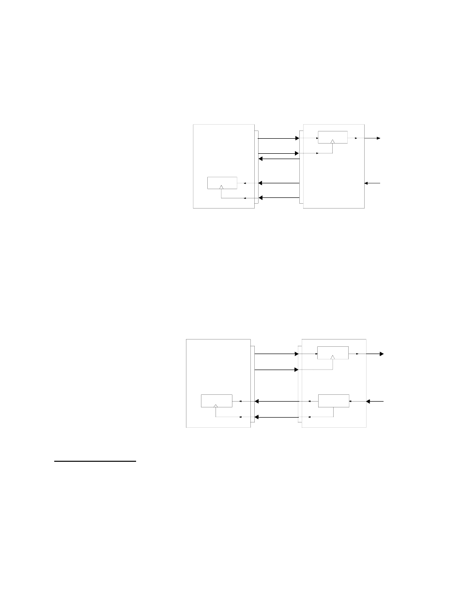
The SD and RD signals have associated clock signals called
Terminal Timing (TT) and Receive Timing (RT). The DIU’s input
buffer may use the TT signal to clock in SD. The customer’s DTE
receive buffer uses the RT signal to clock in RD (Figure 7-4).
Figure 7-4 Terminal Timing (TT) and Receive Timing (RT)
The RT signal is derived by recovering the clock from the data
stream coming from the network. Since the T1 data contains
overhead bits that are removed before being sent to the DTE, the
frequency of this data is different than the frequency of RD. In the
receive direction, the frequency is decreased from 1.544 Mbit/s to
the selected interface frequency. In the transmit direction, the
frequency is increased from the selected interface frequency to
1.544 Mbit/s. (Figure 7-5)
Figure 7-5 Receive Clock Recovery
Send Timing
Send Timing (ST) is used to control the rate at which the DTE
presents transmit data. Send Timing (ST) is also sent by the DIU to
tell the DTE the exact frequency to transmit on the SD and TT leads.
The DTE uses the ST signal to clock data onto the SD lead. (Figure
7-6)
Customer
Equipment
(DTE)
DSU
(DCE)
T1 XMT
T1 RCV
SD
TT
RD
RT
Input Buffer
RCV Buffer
ST
Customer
Equipment
(DTE)
DSU
(DCE)
Receive
Input Buffer
Clock
SD
RD
TT
RT
T1 XMT
T1 RCV
Buffer
Recovery