Tri Tool 648RBL Clamshell Hydraulic 2 Piece User Manual
Page 12
12
TRI TOOL INC.
92-1146 : Rev. 131230
Lightly turn in the remaining Bearing Adjustment Screws in the following order
until all of the Bearings make contact with the Head stock:
3, 4, 22, 23, 12, 13, 32, 33, 5, 6, 24, 25, 14, 15, 34, 35, 7, 8, 26,
27, 16, 17, 36, 37, 9, 28, 29, 18, 19, 38, 39, and 40.
Relax the Bearing Adjustment Screws (1, 40, 19, 20, 10, 11, 30, and 31) and
lightly turn them in until they make contact with the Head Stock.
Connect the Power supply and apply power to the Clamshell so that the
Clamshell is running at full speed.
Lightly adjust the Bearing Adjustment Screws in the following sequence until
the Clamshell rotation slows slightly:
3, 4, 22, 23, 12, 13, 32, 33, 5, 6, 24, 25, 14, 15, 34, 35, 7, 8, 26,
27, 16, 17, 36, 37, 9, 28, 29, 18, 19, 38, 39, and 40.
Listen for a change in the sound of the Drive Motors.
Adjust the Bearing Adjustment Screws in small increments to that the
Bearings are loaded evenly.
All of the Bearing Adjustment Screws should have a torque of at most 1 in-lb
(0.1 N-m) to insure that the bearings are uniformly loaded.
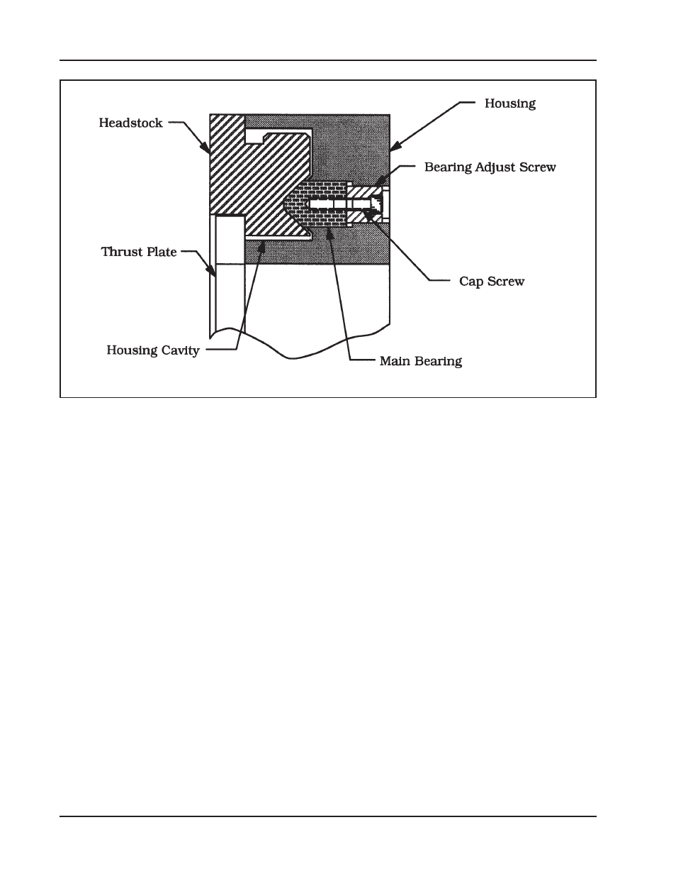
Clamshell Cross Section