4 transducers wiring – Tecfluid CU Series User Manual
Page 9
9
The mA output is galvanically isolated. It can be active (which means that the receiver
device connected to it should have a passive input) or passive (which means that the
receiver device must provide the power supply for the current loop). It is recommended to
use a receptor with an input resistance of less than 700 Ω to guarantee correct operation.
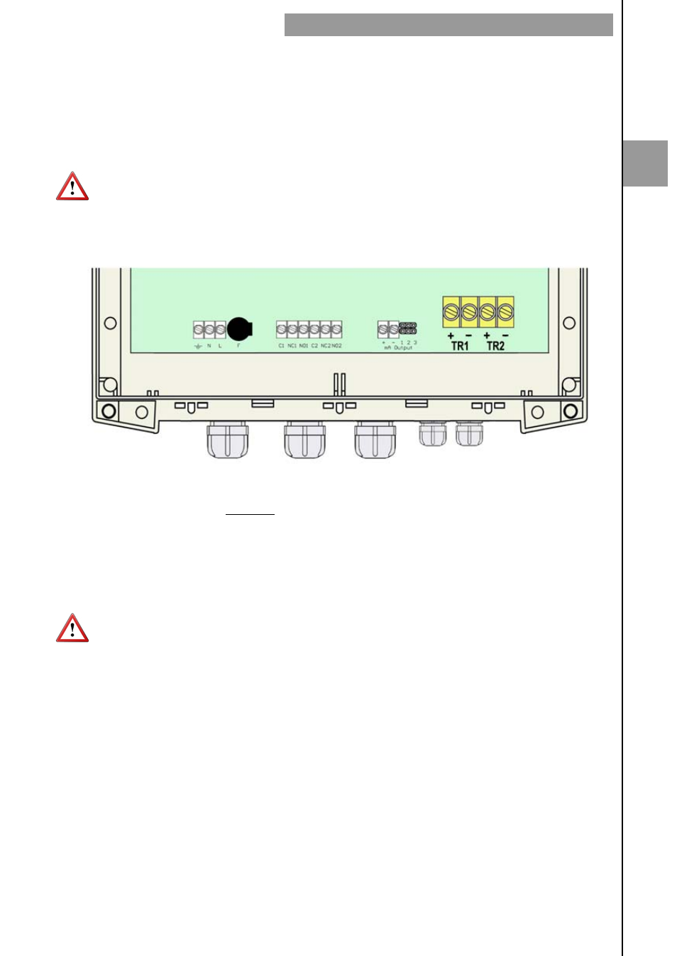
To configure the analog output type (active or passive) there are two jumpers placed just
behind the terminal strip. For the passive mode the jumpers must be situated between
pins 2 and 3 and for active mode the jumpers must be between pins 1 and 2.
NOTE:
The analog output has protection against reversed polarity. Due to another
protection against over voltages, if a loop supply voltage of greater than 32 V is connected
the equipment may be damaged.
2.1.4 Transducers
wiring
Terminal
TR1
+
Live
(positive)
TR1
-
Shield
(negative)
TR2
+
Live
(positive)
TR2
-
Shield
(negative)
The transducers are identified as TR1 and TR2. Be sure to connect the cable TR1 in the
TR1 terminals in the circuit board and the cable TR2 in the TR2 terminals. The exchange
of the transducers can result in a loss of precision of the values measured by the
instrument.
Transducer cables are supplied with plastic indicators 1 and 2 to be connected to the
transducers TR1 and TR2 respectively.
2
INSTALLATION OF THE ELECTRONIC CONVERTER