Super Systems AC20 RS485 Modbus User Manual
Page 6
Page 6/59
TITLE: MODBUS/J-BUS Protocol for SSi’s- AC20 ENG. 824E REV. 1
Function code 1 and 2: Bits reading
These function codes are used by the master unit to request the value of a consecutive
group of bits (max 24) which are representing the status of the slave unit.
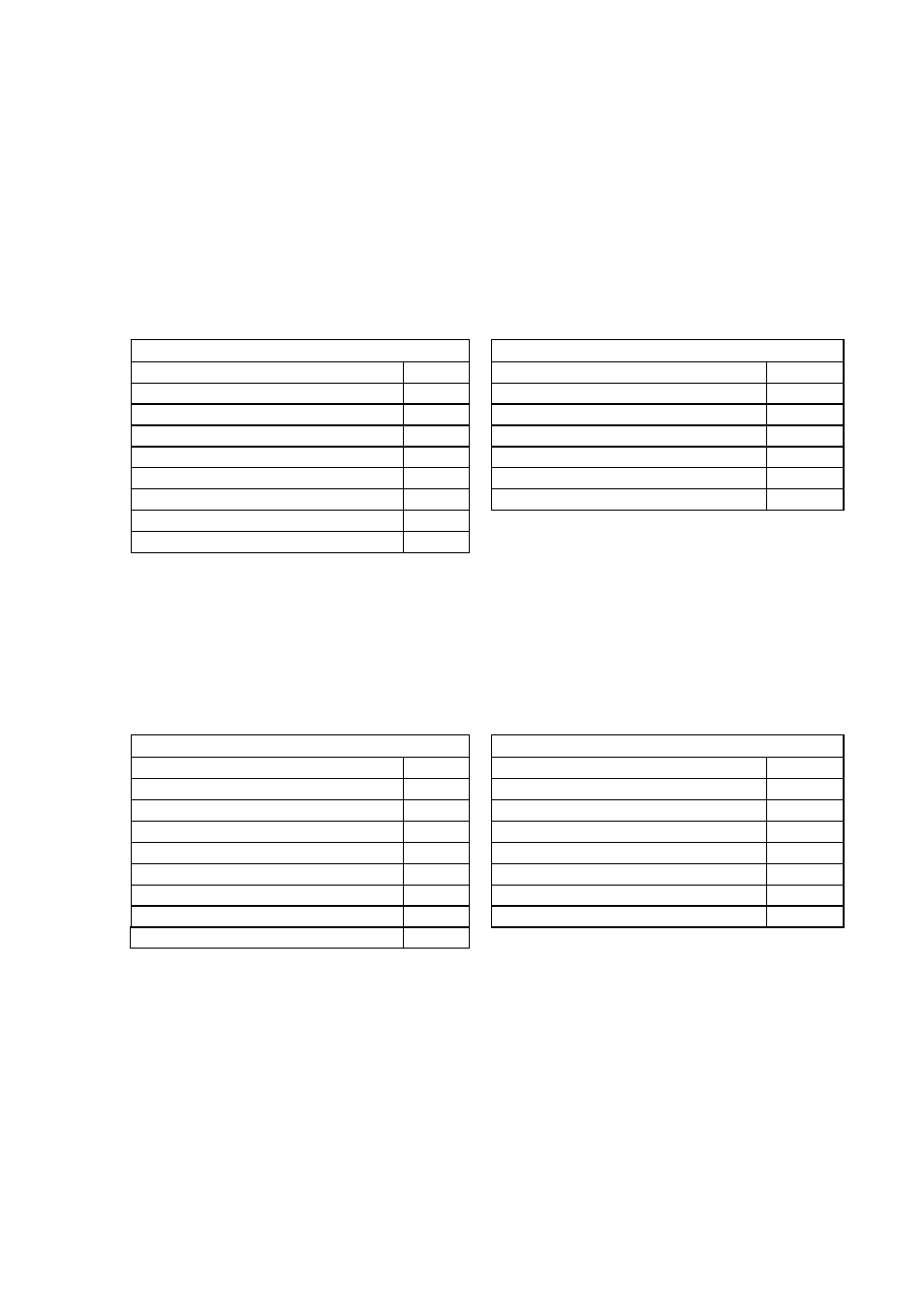
Request from master to slave
Reply from slave to master
Range
Byte
Range
Byte
Slave address (1-255)
1
Slave address (1-255)
1
Function code (01-02)
1
Function code (01-02)
1
Bit starting address (high byte)
1
Byte count (n)
1
Bit starting address (low byte)
1
Data
n
Number of bits (high byte)
1
Error check (CRC-16) (low byte)
1
Number of bits (low byte)
1
Error check (CRC-16) (high byte)
1
Error check (CRC-16) (low byte)
1
Error check (CRC-16) (high byte)
1
The “Data” field indicates the bits requested: the bit with lower address is in the bit 0 of the
first byte, the next is in the bit 1, and so on.
The eventual don’t care bits necessary to complete the last byte are equal to 0.
Example:
Ask to slave at address 100 (64h) the status of 14 (Eh) bits starting from bit 201 (C9h).
Request from master to slave
Reply from slave to master
Range
Byte
Range
Byte
Slave address
64h
Slave address
64h
Function code
01h
Function code
01h
Bit starting address (high byte)
00h
Byte count
02h
Bit starting address (low byte)
C9h
Data
A7h
Number of bits (high byte)
00h
Data
04h
Number of bits (low byte)
0Eh
Error check (CRC-16) (low byte)
8Eh
Error check (CRC-16) (low byte)
64h
Error check (CRC-16) (high byte)
07h
Error check (CRC-16) (high byte)
05h
The 2 bytes in “Data“ field (A7h=10100111b, 04h=00000100b) mean:
bit 201 status = 1
bit 209 status = 0
bit 202 status = 1
bit 210 status = 0
bit 203 status = 1
bit 211 status = 1
bit 204 status = 0
bit 212 status = 0
bit 205 status = 0
bit 213 status = 0
bit 206 status = 1
bit 214 status = 0
bit 207 status = 0
Don’t care
= 0
bit 208 status = 1
Don’t care
= 0