Super Systems AC20 RS485 Modbus User Manual
Page 43
Page 43/59
TITLE: MODBUS/J-BUS Protocol for SSi’s- AC20 ENG. 824E REV. 1
WORDS FOR DEVICE IN CONFIGURATION MODE - PARAMETERS
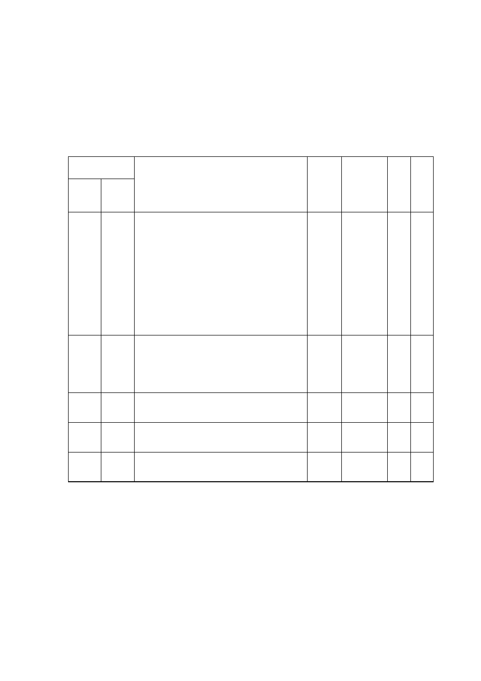
“In.Ot.” - Menu conf. 5 - DIGITAL INPUT/OUTPUT CONFIGURATION
ADDRESS
(decimal)
DEC.
Display
R
W
R
JBus
Mod
Bus
DESCRIPTION
FIGU-
RES
MNEM
CODE
E
A
D
I
T
E
2401
2400
External contact “DIG1” function
Range:
0 = Input contact not used
1 = Input contact used for SP/SP2
auxiliary set point selection
2 = Input contact used for SP3/SP4
auxiliary set point selection
3 = Input contact used for Auto/Manual
selection
4 = Input contact used for output limiter
activation
5 = Input contact used to reset
(acknowledge) alarm
N.A.
(“d1.Fn”)
x
x
2402
2401
External contact “DIG1” logic level
Range:
0 = The input is at logic level “1” when
contact is open
1 = The input is at logic level “1” when
contact is closed
N.A.
(“d1.St”)
x
x
2403
2402
External contact “DIG2” function
Note:
See “External contact “DIG1” function”
N.A.
(“d2.Fn”)
x
x
2404
2403
External contact “DIG2” logic level
Note:
See “External contact “DIG1” logic level“
N.A.
(“d2.St”)
x
x
2406
2405
External contact “DIG3” logic level
Note:
See “External contact “DIG1” logic level“
N.A.
(“d3.St”)
x
x