Super Systems AC20 RS485 Modbus User Manual
Page 40
Page 40/59
TITLE: MODBUS/J-BUS Protocol for SSi’s- AC20 ENG. 824E REV. 1
WORDS FOR DEVICE IN CONFIGURATION MODE - PARAMETERS
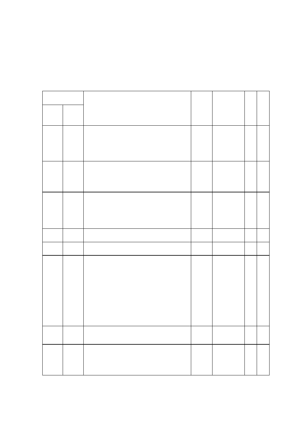
“C.Cn.” - Menu Conf. 3 - CONTROL OUTPUT CONFIGURATION
ADDRESS
(Decimal)
DEC.
Display
R
W
R
Jbus
Mod
Bus
DESCRIPTION
FIGU-
RES
MNEM
CODE
E
A
D
I
T
E
2206
2205
Main control output conditioning
Range
0 = The control output is calculated by the
PID
1 = The control output is complemented
(100-PID calculated value)
N.A.
(“ñC.Cn”)
x
x
2207
2206
Main control output scaleable for display
in eng. unit
Range:
0 = Scaleable is not required
1 = Scaleable is required
N.A.
(“ñ.SCL”)
x
x
2208
2207
Decimal point position for main control
output display in eng. unit
Range:
0 = No decimal figure
1 = One decimal figure
2 = Two decimal figure
N.A.
(“ñC.dP”)
x
x
2209
2208
Low scale range value for main control
output display in eng. unit
See Mbus
word 301
or 2207
(“ñC.E.L.”)
x
x
2210
2209
High scale range value for main control
output display in eng. unit
See Mbus
word 301
or 2207
(“ñC.E.H.”)
x
x
2211
2210
Main control output auxiliary conditioning
Range:
0 = The functions described in the note
are applied “Before” of the “Main
control output conditioning” stage
1 = The functions described in the note
are applied “After” of the “Main control
output conditioning” stage
Note:
a - Control output limiter
b - Control output max rate of rise
c - Control output display value
N.A.
(“ñC.A.C.”)
x
x
2212
2211
Secondary control output conditioning
Note:
See “Main control output conditioning”
N.A.
(“SC.Cn.”)
x
x
2213
2212
Secondary control output scaleable for
display in eng. unit
Range:
0 = Scaleable is not required
1 = Scaleable is required
N.A.
(“S.SCL”)
x
x