Sundance SMT941 User Manual
Page 9
User Manual SMT941
Page 9 of 43
Last Edited: 23/08/2011 17:24:00
MHz VCXO). The distribution chip also allows synchronising the on-board VCXO to a
reference signal that can be external or internal (on-board 10-MHz crystal). External
reference, external sampling clock input and output are accessible on MMCX
connectors. An external trigger input is also available on the board (it is
implemented as an input in the default firmware provided but can also be
implemented as an output).
All control, data and clock lines are mapped onto an SLB connector so the card can
be fully controlled by an SLB FPGA base module (SMT351T for example, with 2.5-
Volt FPGA IOs).
Some green LEDs are available on the board. A group of four LEDs is driven directly
from the SLB base FPGA module and can be used to return status bits. Other
indivudual LEDs should be lit and show that local power supplies are on.
2.2.1 A/D converters
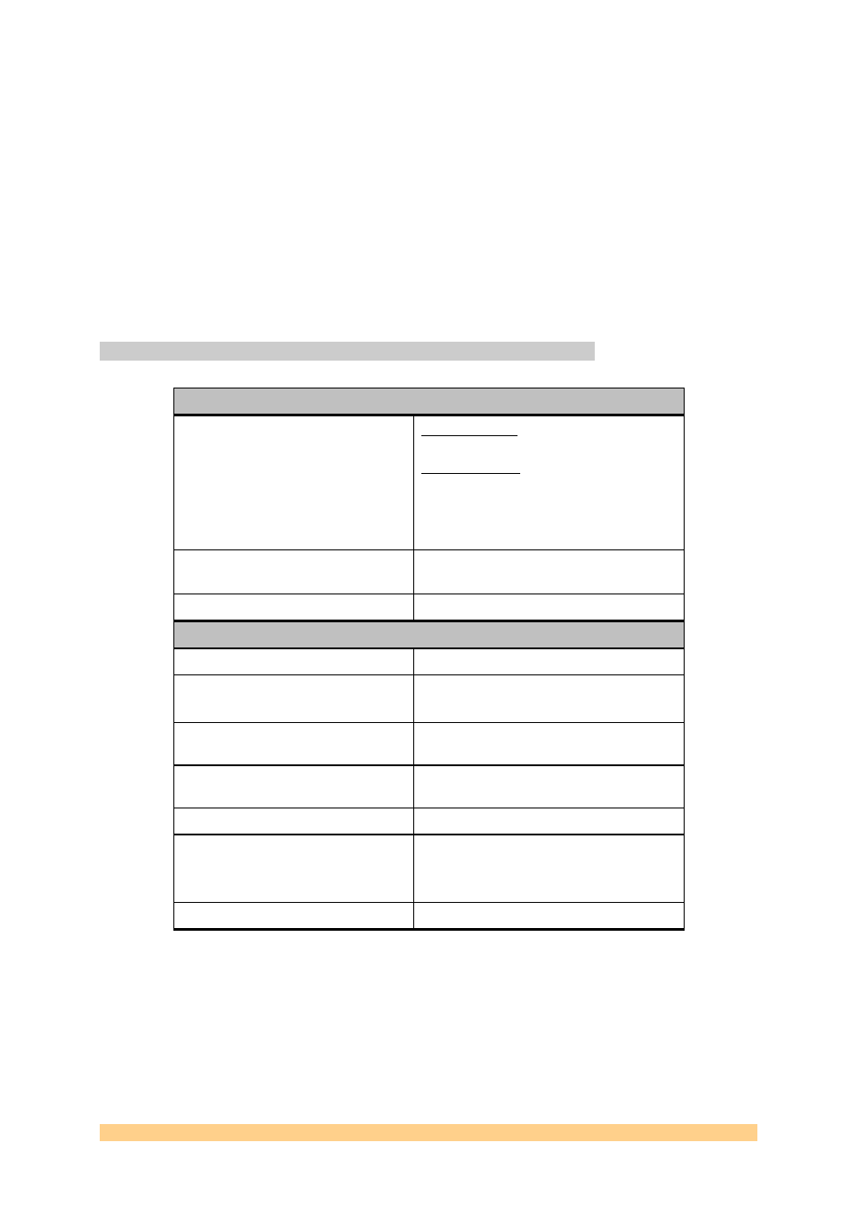
The main characteristics of the SMT941 are gathered into the following table.
Analogue Inputs
Input voltage range
0dB gain setting : 2.3Vpp - Full scale - AC
coupled
6dB gain setting : 1.15Vpp – Full Scale –
AC-coupled
Programmable input gain via register
(0…6dBs) by steps of 0.5dB (coarse gain)
and steps of 0.134dB (fine gain).
Impedance
Single-ended inputs – to be connected to a
50
(AC) source.
Bandwidth
Tbd – depends on ADC internal input gain.
ADC characteristics
Output Data Width per channel
14 Bits
Data Format
2’s Compliment or offset binary
(Changeable via control register)
SFDR
75 (0-db gain) / 82dBs (6-db gain)
maximum (manufacturer)
SNR
69 (0-db gain) / 66dBs (6-db gain)
maximum (manufacturer)
ENOB
11.3 bits maximum (manufacturer)
Maximum Sampling rate
250 MSPS
(1…100MSPS low speed mode)
(100…250MSPS high speed mode)
Minimum Sampling rate
1 MSPS
ADC Analog inputs on the board are single-ended. A double RF transformer
structure is used to provide single-ended to differential conversion. Both
transformers are identical and have a ratio of 1. In order to match the 50-Ohm at
the connector, the output of the second transformer has two 25-Ohm resistors
terminated to the ADC common mode voltage.