Reconfigurable bits – Sundance SMT911 User Manual
Page 29
SMT911 User Manual SMT911
Page 29 of 38
Last Edited: 01/06/2010 10:09:00
synthesizer, and sets the DC current for the charge pump. The programmable
reference frequency divider provides the reference frequency to the phase detector
by dividing the signal of the crystal oscillator.
Byte 1-0
D15 D14
D13
D12
D11
D10
D9
D8
D7
D6
D5
D4
D3
D2
D1
D0
Default
0
0
1
1
1
0
0
0
0
0
1
0
0
1
0
0
Reconfigurable bits:
Bit
Default
Description
13
0
„0‟ = normal operation, „1‟ = MIMO applications
10
0
These Bits set the VCO Sub-Band when programmed by using SPI (Bit8=1).
“00” = lowest frequency band; “11” = highest frequency band.
9
0
8
0
VCO SPI Bandswitch Enable. “0” = disable SPI control, bandswitch is done by
FSM; “1” = bandswitch is done by SPI programming.
7
0
VCO Bandswitch Enable. “0” = disable; “1” = start automatic bandswitch.
6
0
RF Frequency Band Select in 802.11a Mode (Bit0=1). “0” = 4.9GHz to 5.35GHz band; “1” = 5.47GHz
to 5.875GHz Band.
5
0
PLL Charge-Pump-Current Select. “0” = 2mA, “1” = 4mA.
3
0
These Bits Set the Reference-Divider Ratio. “001” corresponds to R = 1 and “111” corresponds to R
= 7.
2
0
1
0
0
0
RF Frequency Band Select. “0” = 2.4GHz Band; “1” = 5GHz band.
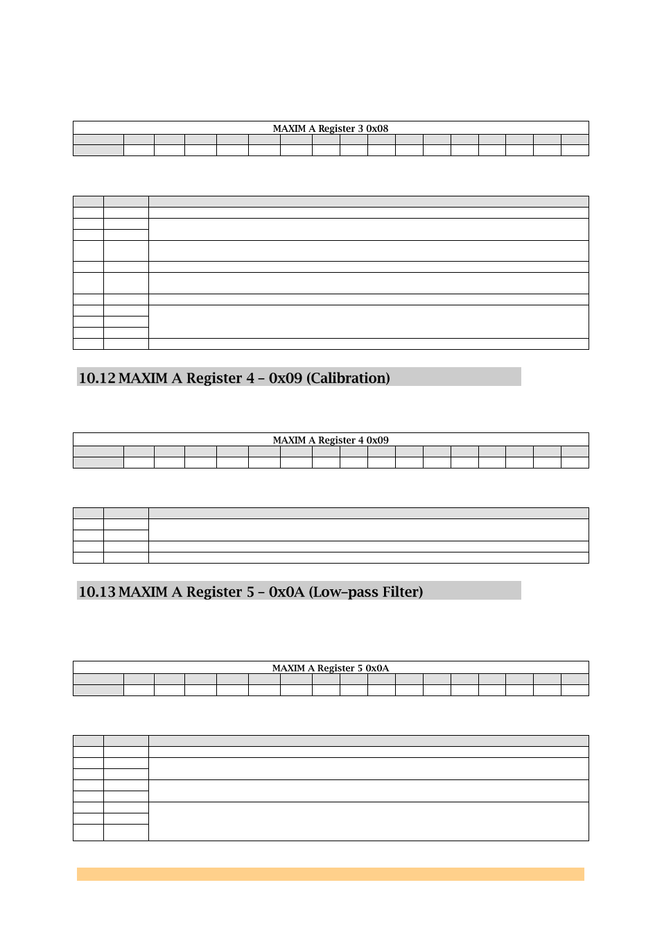
This register configures the TX/RX calibration modes.
Byte 1-0
D15 D14
D13
D12
D11
D10
D9
D8
D7
D6
D5
D4
D3
D2
D1
D0
Default
0
0
0
1
1
1
0
0
0
0
0
0
0
0
0
0
Reconfigurable bits:
Bit
Default
Description
12
1
Transmitter I/Q Calibration LO Leakage and Sideband-Detector Gain-Control Bits.
“00” = 8 dB; “01” = 18 dB; “10” = 24 dB; “11” = 34 dB
11
1
1
0
“0” = TX Calibration Mode Disabled; “1” = TX Calibration Mode Enabled
0
0
“0” = RX Calibration Mode Disabled; “1” = RX Calibration Mode Enabled
This register allows the adjustment of the RX and TX low-pass filter corner
frequencies
Byte 1-0
D15 D14
D13
D12
D11
D10
D9
D8
D7
D6
D5
D4
D3
D2
D1
D0
Default
0
0
0
0
0
0
0
0
0
0
1
0
1
0
1
0
Reconfigurable bits:
Bit
Default
Description
11
0
RSSI High Bandwidth Enable. “0” = 2 MHz; “1” = 6MHz
6
0
TX LPF Corner Frequency Coarse Adjustment. “00” = undefined; “01” = 12MHz (nominal
mode); “10” = 18MHz (turbo mode 1); “11” = 24MHz (turbo mode 2).
5
0
4
0
RX LPF Corner Frequency Coarse Adjustment. “00” = 7.5MHz; “01” = 9.5MHz (nominal
mode); “10” = 14 MHz (turbo mode 1); “11” = 18MHz (turbo mode 2).
3
0
2
0
RX LPF Corner Frequency Fine Adjustment (Relative to the Course Setting).
“000” = 90%; “001” = 95%; “010” = 100%; “011” = 105%; “100” =110%.
1
0
0
0