5 pll setup registers (write add 0x802 – 0x809), 6 data source selection (write add 0x80e), Pll setup registers (write add 0x802 – 0x809) – Sundance SMT381 2007 User Manual
Page 30: Data source selection (write add 0x80e), Figure 20: pll setup registers (write only), What follows applies for channel a and b
11.1.5 PLL Setup Registers (Write Add 0x802 – 0x809)
These registers set up the frequency of the PLL circuit on the SMT381. There are two
sets of registers – one set for setting up the IF side of the PLL, and the other set for
setting up the RF side of the PLL. The IF side is unconnected, while the RF side is
connected to a 600 – 1200 MHz VCO circuit which is divided by two before entering the
DAC at a frequency of 300 – 600MHz. All registers must be initialized, and only when
writing to the final register will both the IF and RF side be configured to their new
values.
31 .. 28
27 .. 24
23 .. 20
19 .. 16
15 .. 12
11 .. 8
7 .. 4
3 .. 0
Command
Address
Data MSB
Data LSB
0x1
0x1
0x1
0x1
0x1
0x1
0x1
0x1
0x802
0x803
0x804
0x805
0x806
0x807
0x808
0x809
Not Used
Not Used
Not Used
Not Used
Smt381Pll_RfR_Reg1
Smt381Pll_RfR_Reg2
Smt381Pll_RfN_Reg1
Smt381Pll_RfN_Reg2
Not Used
Not Used
Not Used
Not Used
Smt381Pll_RfR_Reg1
Smt381Pll_RfR_Reg2
Smt381Pll_RfN_Reg1
Smt381Pll_RfN_Reg2
Figure 20: PLL Setup Registers (Write Only)
For a detailed description of the configurable bits in the PLL registers please refer to the
“PLL Configuration” section under “Firmware Building Blocks” at the end of this
document.
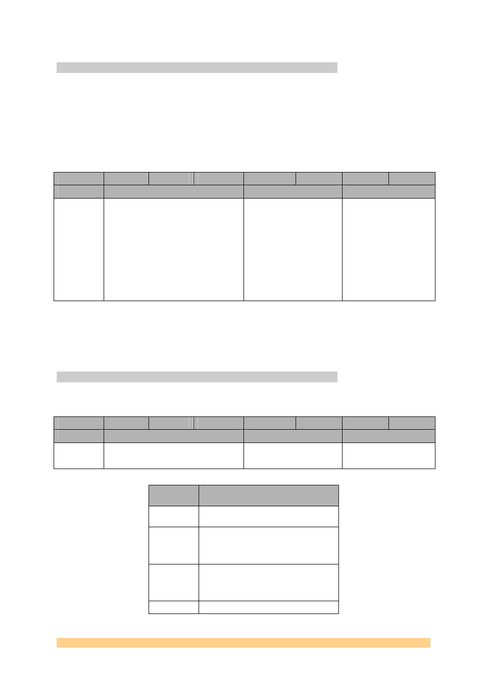
11.1.6 Data Source Selection (Write Add 0x80E)
This register selects between four data sources.
31 .. 28
27 .. 24
23 .. 20
19 .. 16
15 .. 12
11 .. 8
7 .. 4
3 .. 0
Command
Address
Data MSB
Data LSB
0x1
0x80E Not
Used 6..4
: Channel B selection
2..0 : Channel A selection
What follows applies for Channel A and B:
Register
Value
Channel Data Source
0x0
Look Up Table - A Fixed sine period is
stored into a block of ROM as 32 samples.
0x5
SHB to DPRAM – In this mode, 32
samples per channel are loaded via SHB to
be played back continuously and sent to
the DAC.
0x6
SHB to DAC – Samples coming the SHBs
are routed directly to the DAC. A 256-word
(32 bits) FIFO connects the SHB interface
to the DAC.
0x7
RSL to DAC – Samples coming out of the
User Manual SMT381
Page 30 of 31
Last Edited: 12/06/2007 10:43:00