2 main analogue features, 3 clock structure, Main analogue features – Sundance SMT381 2007 User Manual
Page 10: Clock structure
The sampled data can either be supplied to the DAC cores externally via its LVDS data
bus or internally from the Waveform Memory Module. The data may be routed to the
DAC cores through a number of paths. The most direct path routes data straight from
the LVDS input buffers to the DAC core input latches. All digital functions on the
module are controlled by the FPGA of the base board.
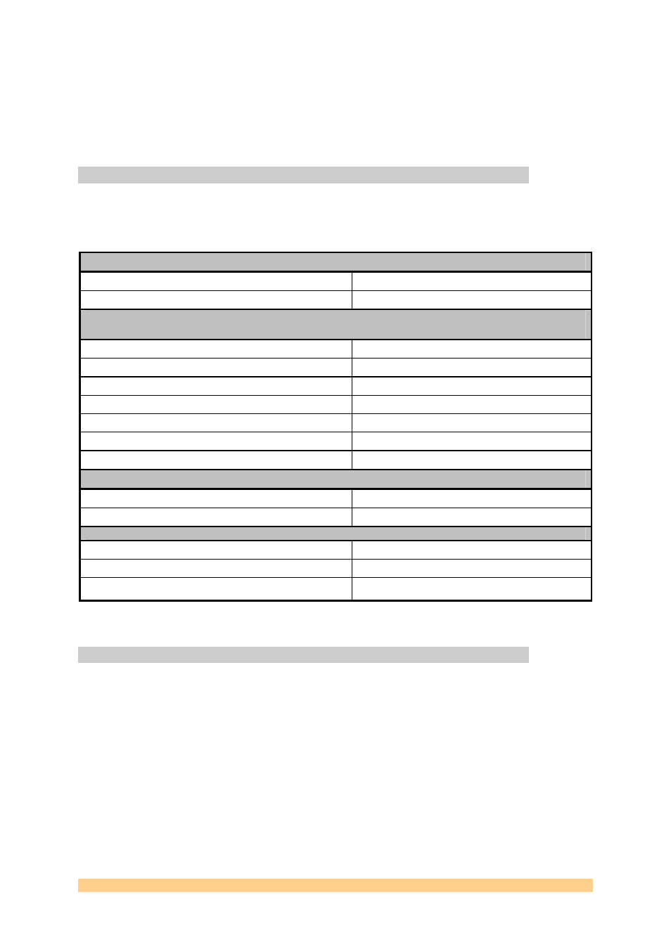
4.2 Main analogue features
The main analogue characteristics of the SMT381 are listed in the following table:
Analogue outputs
Output current range
20mA
Data Format
Analogue current
External sampling clock inputs (The clock frequency is divided by 2 on the SMT381 for a DDR clock for
the DAC)
LVPECL Clock
Signal format
LVPECL
Frequency range
25MHz to 1000 MHz
RF Clock
Signal format
Sinus wave
Frequency range
25MHz to 1000 MHz
Amplitude 0dBm
Typ
External trigger inputs
Signal format
LVPECL
Frequency range
DC to 100 MHz
DAC performance @
Single tone at -1dBFS, 800MSa/s, DC to 400MHz (From DAC datasheet)
Spurious Free Dynamic Range (SFDR) @ 20MHz
75dBc
Spurious Free Dynamic Range (SFDR) @ 300MHz
58dBc
Cross-talk 4 tone test, each tone at -15dBFS, centred at
276MHz
67dBc
Table 1: main analogue features
4.3 Clock structure
There are two integrated clock generators on the module. The user can either use these
clocks or provide the module with an external clock (input via MMBX connectors). The
following figure shows the SMT381 clock tree.
User Manual SMT381
Page 10 of 31
Last Edited: 12/06/2007 10:43:00