4 analogue output, Analogue output – Sundance SMT381 2007 User Manual
Page 12
The selected clock then drives the DAC and is also distributed to the base board for data
synchronization purposes. On the FPGA of the base board a PLL synchronizes the clock
with the data being sent by using the supplied clock and looping that same clock to the
DAC and back. This technique synchronizes the clock to the data is being sent out on
(base board side) even further with the clock used in the DAC. Synchronization issues
become a bigger factor as the clock frequencies get bigger.
All the clock control is done on the base board in firmware on the FPGA.
4.4 Analogue output
Two options are hardwired into the design. The options are shown below with a figure of
each.
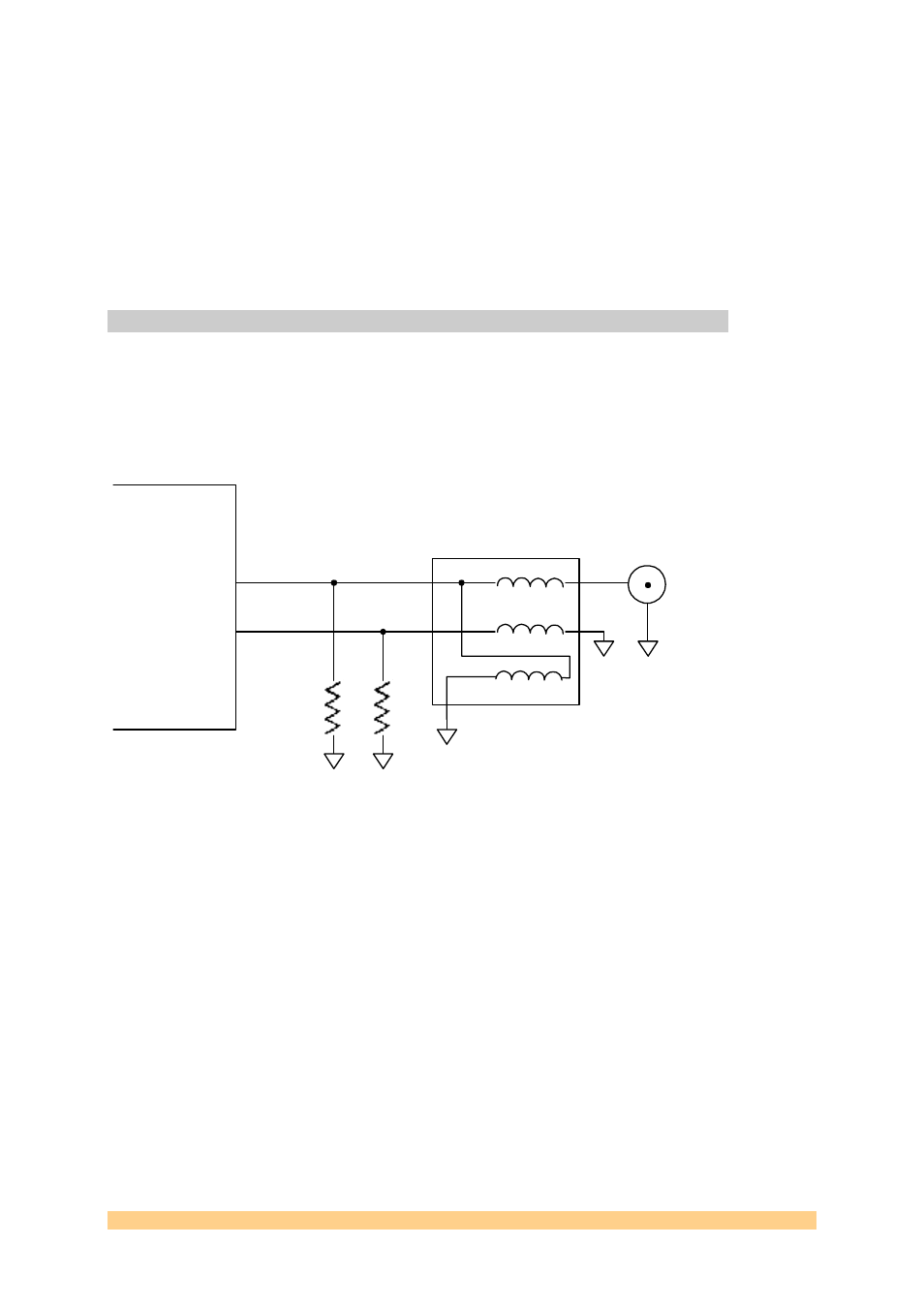
Option 1
Single ended AC coupled output with Macom TP-101 transformer.
R1
R1
TP101
+
-
Output
Connector
Figure 3. Option 1 for the SMT381 analog output stage.
Option 2
Differential DC coupled output with + and – channels going to separate connectors
User Manual SMT381
Page 12 of 31
Last Edited: 12/06/2007 10:43:00