3 tim config, 3 interface description, 1 mechanical interface – Sundance SMT368 User Manual
Page 15: 2 electrical interface, Tim config, Interface description, Mechanical interface, Electrical interface
4.2.3 TIM config
The TIM config is a special reset feature. This signal comes from the TIM connector (P1), pin
74, and it is available to the CPLD.
TIM Config is driven by another module on the same carrier board, for instance from a DSP
module running an application (see the Cha
SMT6400)
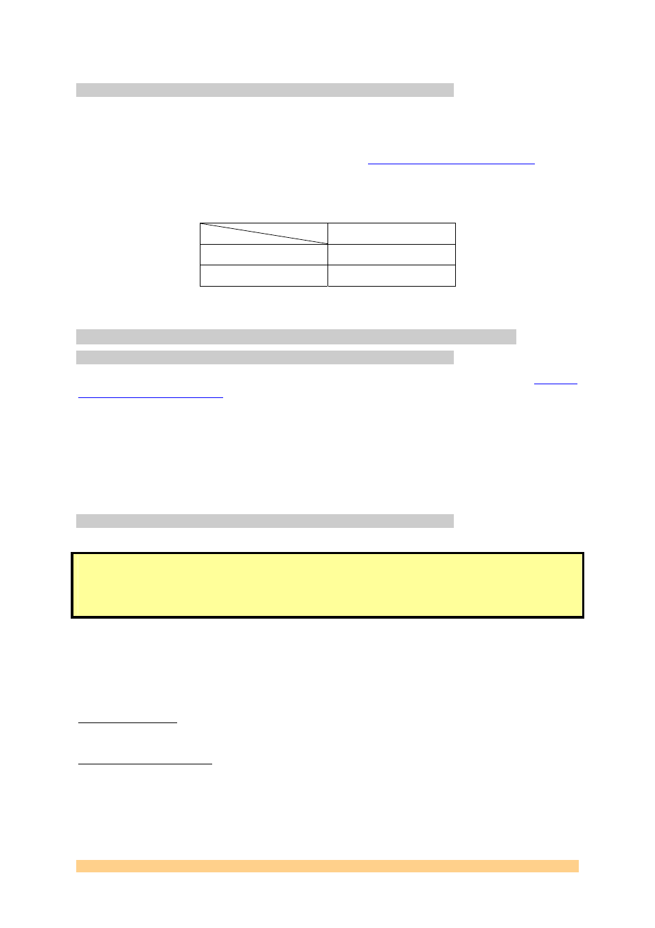
It can be enabled with the DIP swith SW1:
TIM Config
SW1 Position
POS4
ENABLED
ON
DISABLED
OFF
Table 4: SW1 DIP switch for the configuration mode selection
4.3 Interface Description
4.3.1 Mechanical Interface
This module conforms to the TIM standard (Texas Instrument M
) for single width modules.
It sits on a carrier board.
The carrier board provides power, Ground, communication links (ComPort links) between all
the modules fitted and a pathway to the HOST, for a non stand-alone system.
The SMT368 requires an additional 3.3V power supply (as present on all Sundance TIM
carrier boards), which must be provided by the two diagonally opposite mounting holes.
4.3.2 Electrical Interface
Do NOT connect any external TTL (5V) signals to the SMT368 I/Os as the FPGA
is NOT 5V compliant. This implies that the ComPorts and global bus lines of the
carrier board MUST be LVTTL and that any device driving signals on the SHB
connectors must drive at LVTTL (3.3V).
This module must have the +5V supplied through the TIM connectors. The SMT368 requires
an additional 3.3V power rail (compatible and present on all the Sundance’s carrier boards),
which must be provided by the two diagonally opposite mounting holes.
DC/DC Converter:
An on-board DC-DC converter is used to supply power to the FPGA core.
Linear Voltage regulator:
Linear regulation is provided for the Vcco banks of the FPGA that are connected to the SLB
when used in 2.5V mode (LVDS_25).
User Manual SMT368
Page 15 of 24
Last Edited: 31/12/2008 13:53:00