Studio Technologies 50 2000 User Manual
Page 9
Model 50/51 User Guide
Issue 4, July 2000
Studio Technologies, Inc.
Page 9
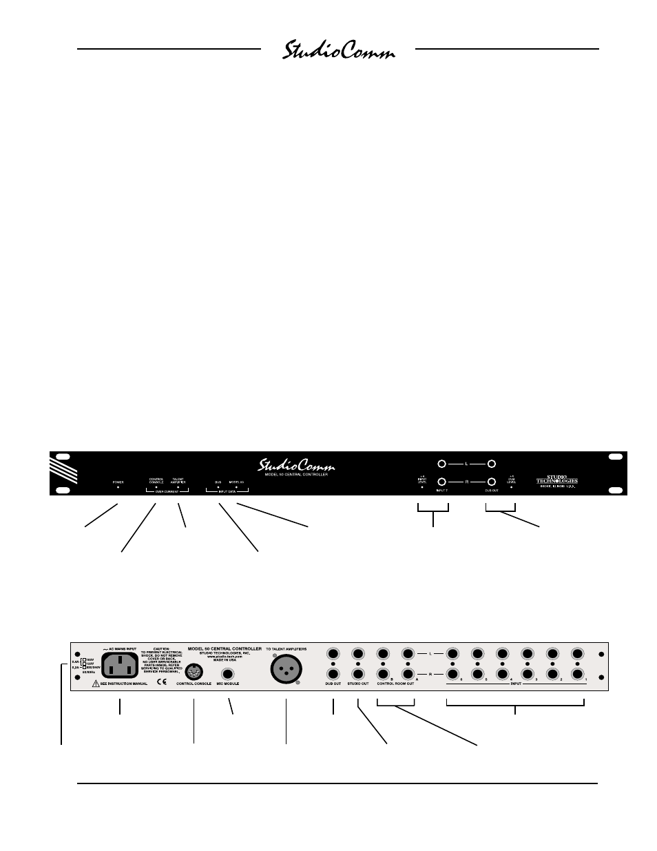
Mic Module
input
Model 50 Back Panel
Model 50 Front Panel
Power
present LED
Stereo line input 7;
LED indicates
+4dBu configuration
Input data
present LED
Talent Amplifier
over current LED
Dub output;
LED indicates +4dBu
configuration
Model 51
Control Console
over current LED
Model 50
input data LED
AC mains
connection
To/from Model 51
Control Console
Output to talent
amplifiers
Control room
A & B outputs
Studio output
Mains voltage
configuration
chart
messages. The Model 51 Control Console
speaks this language, and in most
applications a Model 51 will be utilized. In
special applications the Model 50 Central
Controller can be connected directly to a
MIDI bus, allowing the creation of a fully
automated recording or audio routing
system. (For more information on MIDI
support, refer to Appendix A.)
Configuration
The Model 51 Control Console can be
configured to make the system meet a
users exact operating environment. As
previously discussed, each of the seven
stereo line inputs can be independently
set for 10dBV or +4dBu operating levels.
They also can be set for either mono or
stereo operation. In the mono mode a
signal connected to the left input is sent to
the left and right outputs. The dub output
level can be set for a nominal 10dBV or
+4dBu output level.
Unique to the system is the ability to
configure the dim level to one of six val-
ues, ranging from full mute to a modest
10dB reduction. The auto dim off function,
when configured, allows any change in
the control room level potentiometer to
automatically turn off an active dim state.
The talk to phones function can be config-
ured to either interrupt the source selected
for headphone audio and connect com-
munications audio, or to have the commu-
nications audio added (summed or mixed)
with the headphone audio.
The slate function can be configured to
talk to the dub output, or talk to both the
Stereo line
inputs 1-6
Dub
output