Studio Technologies 50 2000 User Manual
Page 18
Issue 4, July 2000
Model 50/51 User Guide
Page 18
Studio Technologies, Inc.
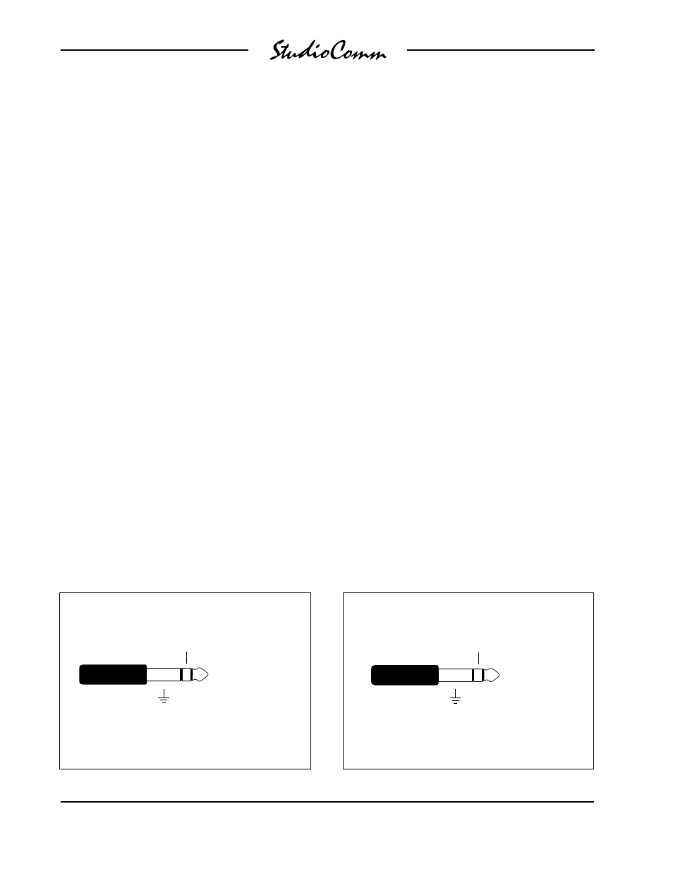
External Communications Switches
Sleeve
(Ground)
Tip (Talk to studio)
Ring (Talk to phones)
(Switchcraft No. 297, Neutrik NP3C, or equivalent)
Tip
(+12Vdc)
Sleeve
(Ground)
Mic Module Input
Ring (Communications
Audio Input)
(Switchcraft No. 297, Neutrik NP3C, or equivalent)
While the Model 51s talk to studio and
talk to phones buttons can be configured
to latch, the remote control inputs are
always push to activate. This is provided
as a safety feature preventing an external
user from latching one of the functions
to the on state.
Mic Module Input
The Model 51 Control Console contains
a microphone which provides the audio
source for the Model 50s communications
functions. In special applications the
Model 51 may not be used, and a sepa-
rate source of communications audio will
be necessary. The Mic Module input on
the back panel of the Model 50 allows the
Model 71 Mic Module to be directly con-
nected. The Model 71 consists of a small
enclosure, about the size of a personal-
computer mouse, containing a micro-
phone and preamplifier. Contact Studio
Technologies for further details about the
Model 71.
Even if you are using the Model 51 Control
Console you may want to provide an
alternate source of communications audio.
To use your own microphone and
preamp, directly connect it using the Mic
Module input jack. The Mic Module input
is a ¼-inch 3-conductor phone jack with
+12Vdc on tip, audio input on ring, and
ground on sleeve. The audio input re-
quires a nominal 10dBu signal (10dBu,
not 10dBV!). The +12Vdc on the tip is
from the same source that powers the
Model 51, and is provided to power the
Model 71 Mic Module. If you feel the urge
to use this power source, be aware that it
only provides 110 milliamps of current of
which the Model 51 needs about 100mA.
So go ahead and use all the current you
need, as long as it doesnt exceed 10mA!
Note: Communications audio from the
Model 51 is routed into the Model 50s
circuitry through the normal connection on
the ring contact of the Mic Module input
jack. When a phone plug is inserted into
the Mic Module input, the audio path from
the Model 51 to the Model 50 is broken.
This means you cant use the Model 51s
microphone and the Mic Module input at
the same time.