Installation – Studio Technologies 74 User Manual
Page 8
Model 74/75 User Guide
Issue 2, January 2006
Studio Technologies, Inc.
Page 9
for Surround
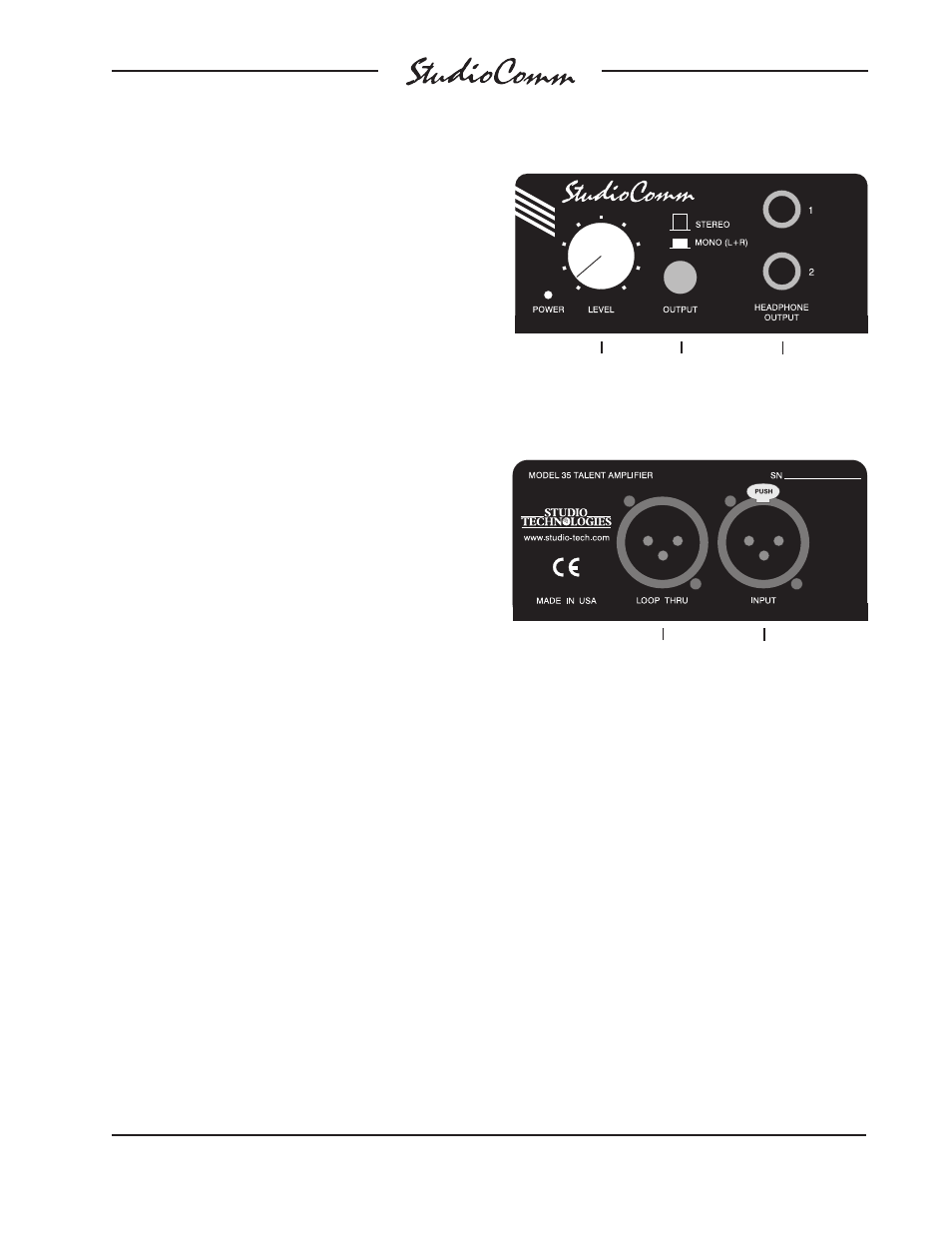
Level control
Stereo/
mono
switch
Headphone
outputs
Figure 4. Model 35 Talent Amplifi er Front Panel
Figure 5. Model 35 Talent Amplifi er Back Panel
To additional
Model 35
Talent Amplifi ers
From Model 74
or another Model 35’s
loop thru connector
For fl exibility, the system is designed to
easily integrate with recording consoles,
specialized playback systems, and audio-
for-picture machine-control electronics.
Four hard-wired remote-control input func-
tions are provided: mute all, dim, talkback,
and input select. By providing access to
the StudioComm’s mute all and dim func-
tions, talkback or slate activity from an
audio console or other communications
system can control the monitor output
level. The remote talkback input allows
an externally provided contact closure or
logic signal to control the talkback function.
This allows easy integration with additional
wired or wireless talkback devices. The
remote input select function is provided
expressly for audio post applications, al-
lowing automatic switching of the Studio-
Comm’s input source whenever the mode
of a recording system changes between
playback and record. This function, re-
ferred historically as PEC/direct switching,
allows accurate monitoring during dialog
replacement, Foley, or other overdub
sessions.
In most cases Model 35 Talent Amplifi er
modules will serve as the user’s head-
phone control center. Each Model 35
contains amplifi er circuitry, stereo level
control, mono switch, and two output jacks.
For convenience, a microphone mounting
stand adapter is included with each Model
35. In addition to the talent amplifi er out-
put, the Model 74 also provides a stereo
line-level cue output. This allows interfac-
ing with other headphone cue systems or
could connect to a transmission system
associated with a remotely located studio
or control room. The line-level cue output
can also serve as a source of “slate” audio
for workstations.
Installation
In this section you will be installing the
Model 74 Central Controller in an equip-
ment rack. Audio input, monitor output,
and headphone cue system connections
will be made. One or more Model 35 Tal-
ent Amplifi ers will be connected. A location
will be selected for the Model 75 Control
Console and it will be connected to the
Model 74. If required, external equipment
will be interfaced to the remote control
inputs. AC mains power will be connected
to the Model 74.