Headphone cue system – Studio Technologies 74 User Manual
Page 11
Issue 2, January 2006
Model 74/75 User Guide
Page 12
Studio Technologies, Inc.
for Surround
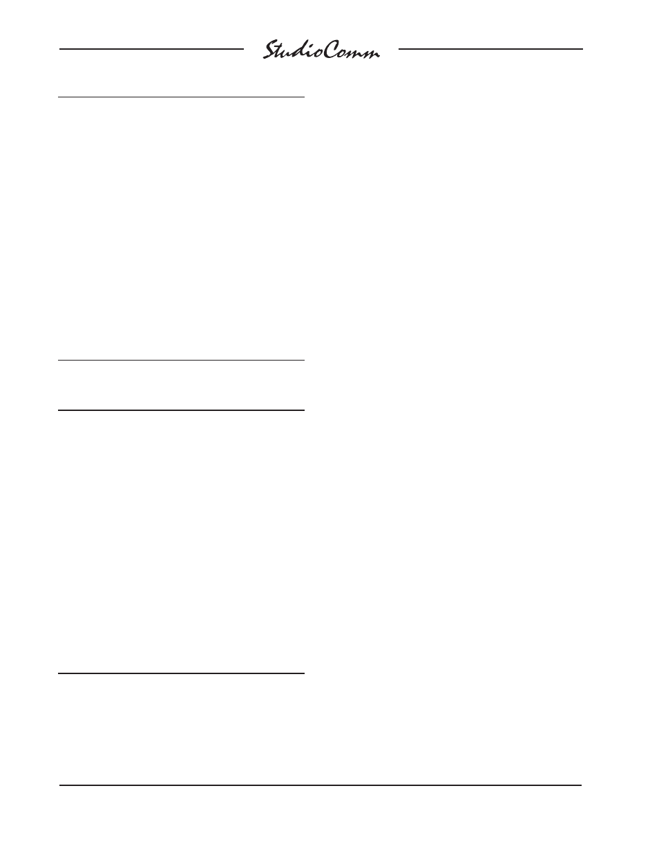
Signal Signal
Connections
High (+)
Low (–) Shield
MONITOR
OUT
A-L
24
12 25
MONITOR
OUT
A-R 10
23 11
MONITOR
OUT
A-C 21
9
22
MONITOR
OUT
A-LFE 7
20
8
MONITOR
OUT
A-LS 18
6
19
MONITOR
OUT
A-RS 4
17
5
CUE
OUT-L
15
3
16
CUE
OUT-R
1
14
2
Notes: 1) Connector type on Model 74 is 25-pin D-subminiature
female. Installer must provide plug (male). Connector
uses 4-40 threaded inserts for locking with mating plug.
2) Wiring scheme follows TASCAM DA-88 convention.
Standard DA-88-type wiring harnesses are directly
compatible, with the exception of 4-40 screw threads
being
required.
Figure 8. Connections for Monitor Output A and
Line-Level Cue Outputs
Signal Signal
Connections
High (+)
Low (–) Shield
MONITOR
OUT
B-L
24
12 25
MONITOR
OUT
B-R 10
23 11
MONITOR
OUT
B-C 21
9
22
MONITOR
OUT
B-LFE 7
20
8
MONITOR
OUT
B-LS 18
6
19
MONITOR
OUT
B-RS 4
17
5
UNUSED
15
3
16
TALKBACK
INPUT
1
14
2
Notes: 1) Connector type on Model 74 is 25-pin D-subminiature
female. Installer must provide plug (male). Connector
uses 4-40 threaded inserts for locking with mating plug.
2) Wiring scheme follows TASCAM DA-88 convention.
Standard DA-88-type wiring harnesses are directly
compatible, with the exception of 4-40 screw threads
being
required.
Figure 9. Connections for Monitor Output B and
Line-Level Talkback Inputs
Note that while the Model 74’s electronically
balanced output circuits are capable of driv-
ing loads of 600 ohms or greater, the output
level will drop slightly as the load impedance
approaches 600 ohms. A 0.5 dB difference
in output level can be expected as the load
impedance changes from 10 k ohms to 600
ohms. This drop is not insignifi cant and leads
to the recommendation that input loads be
10 ohms or greater.
It’s important to note that the two 6-channel
monitor outputs can be used to create a
wide variety of monitor system implementa-
tions. Confi guration choices allow the two
outputs to perform tasks more nuanced
than just serving as a 6-channel A/B
switching matrix. Please carefully review
the confi guration section of this user guide
prior to connecting to the monitor outputs;
don’t let the system’s unique fl exibility go
underutilized!
Headphone Cue System
Two outputs and one input are associated
with the headphone cue system. The talent
amplifi er output supplies audio and DC
power for supporting Model 35 Talent
Amplifi er units. Using this method a great-
sounding, fl exible cue system can be easily
created. A stereo line-level output associ-
ated with the headphone cue system is also
available. A source of line-level audio can be
connected and can serve as the talkback au-
dio source. This source can be used in place
of the microphone contained in the Model 75
Control Console.
Talent Amplifi er Output
Up to four Model 35 Talent Amplifi ers can
be connected to the Model 74’s talent ampli-
fi er output. The output connector is a 3-pin
male XLR-type. For best performance, use
low-capacitance shielded microphone-type