Installation, Installing tsunami in a dcc-ready locomotive, Solder wires to ‘cup’ side of 8-pin connector – SoundTraxx Tsunami Installation User Manual
Page 30
Tsunami Installation Guide
Page 27
Tsunami Installation Guide
Page 27
Installing Tsunami in a DCC-ready Locomotive
If your locomotive is wired with an NMRA-compatible 8-pin socket, you
may solder a mating connector to the DSD’s wire harness, which will allow
you to easily install the decoder by simply plugging the connector into the
socket, with the exception of the speaker and cam connections. SoundTraxx
offers P.N. 810123, which is a package of four connectors that meet NMRA
specifications. Wire the connector as follows:
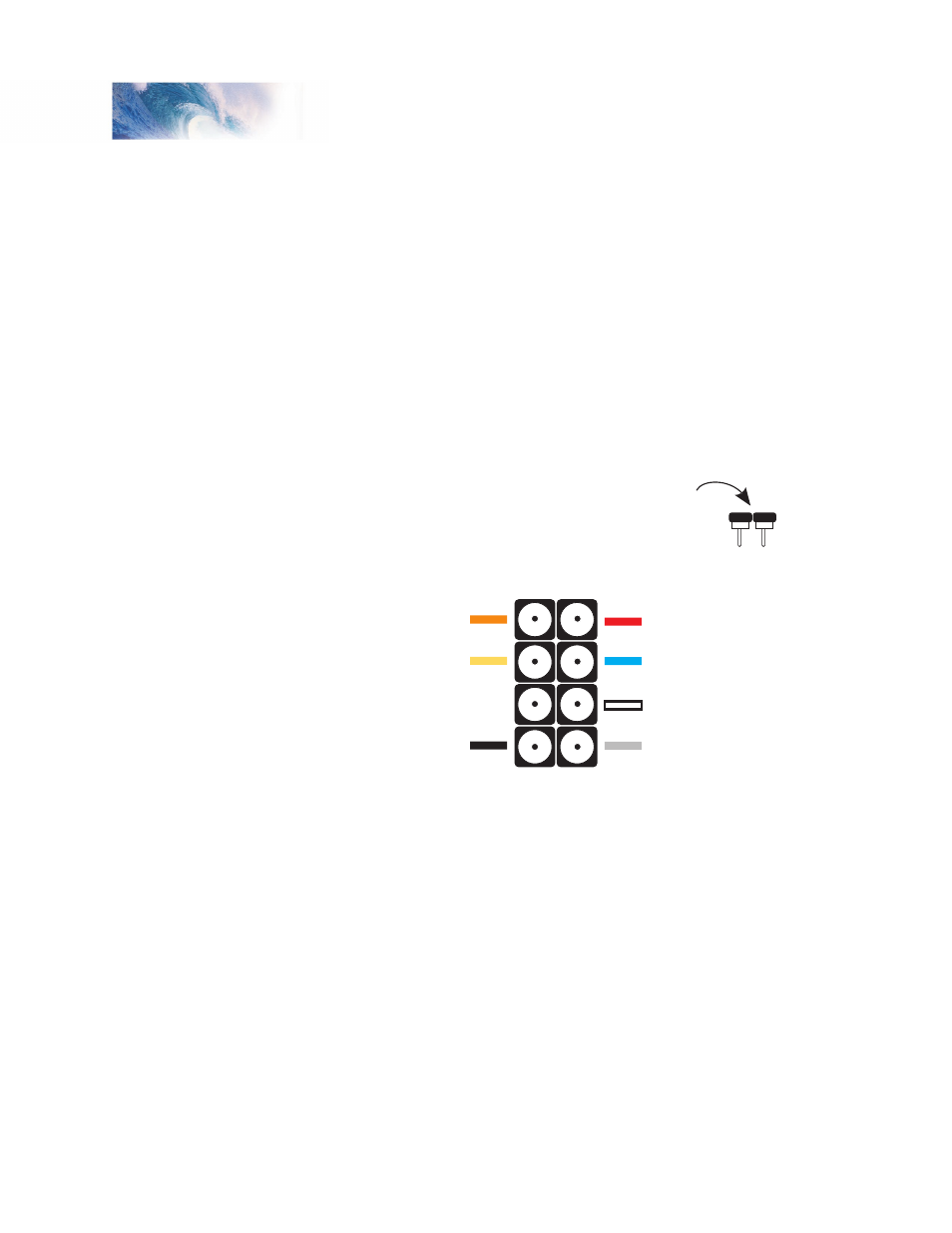
Solder the wires from the sound decoder to the cup side of the connector
as shown in the Figure 24. Speaker and cam wires are not soldered to this
connector.
1. Wire the decoder according to the illustration. Before plugging in the
decoder, we highly recommend you perform a simple test on the socket
itself to ensure it is properly wired. Never assume this socket has been
wired correctly at the locomotive factory!
Figure 24 - NMRA 8-Pin Connector Wiring Code
2. Remove the ‘dummy’ plug from the NMRA socket.
3. Using an Ohmmeter, test the motor connections by touching one probe
to Pin 1 and the other to Pin 8. You should see no response from the
meter. Now touch one probe to Pin 1 and the other to Pin 4. Again, you
should see no response. Repeat this procedure with Pin 5 and Pin 8,
then Pin 5 and 4.
4. Now test the headlight connections by repeating the above procedure
with Pins 8 and 2, Pins 8 and 6 and Pins 8 and 7.
5. Continue the test with Pins 4 and 2, Pins 4 and 6, and Pins 4 and 7.
Remember, you should see no response from the Ohmmeter!
6. Now plug the newly wired connector into the socket with the orange wire
at pin 1 on the manufacturers circuit board. Most manufacturers have
labeled the sockets with pin 1 or pin 8 (at a minimum). Once you have
plugged in the 8-pin connector, you will still need to wire the speaker and
cam according to the instructions for a non DCC-ready decoder.
Solder wires to ‘cup’ side
of 8-pin connector
Motor Right (Orange)
Rear Light (Yellow)
Not Used
Left Rail (Black)
Right Rail (Red)
Function Common (Blue)
Headlight (White)
Motor Left Gray
Pin 1 Pin 8
Pin 4 Pin 5
Installation