Installation, Step 4. isolate the motor, Motor – SoundTraxx Tsunami Installation User Manual
Page 17
Tsunami Installation Guide
Page 14
Tsunami Installation Guide
Page 14
Step 4. Isolate the Motor
The two motor brush connections must be electrically isolated so they are
driven exclusively by the DSD motor outputs. We’re not kidding about this!
Nowadays, many locomotives are being designed and sold as ‘DCC-ready’.
Unfortunately, this means different things to different manufacturers, but it
generally means that this step has been taken care of for you. In the case of
a ‘DCC-ready’ locomotive, follow the instructions on page 27.
Failure to properly isolate the motor will damage your decoder and turn
it into an effective, but short-lived smoke generator!
Begin motor isolation by removing the body shell from the locomotive and in
the case of a steam locomotive, the tender shell as well.
Before you proceed further, it is important to carefully examine the
locomotive wiring and determine where each wire goes and what it does.
The manufacturer’s assembly drawings may be useful here or you may elect
to create your own wiring diagram. In particular, you will need to identify the
connections to the left and right power pickups as well as the (+) and (-)
motor connections. Note: for N, HO, and S scale locos, the positive motor
connection is the one connected to the right rail (engineer side) power
pickup.
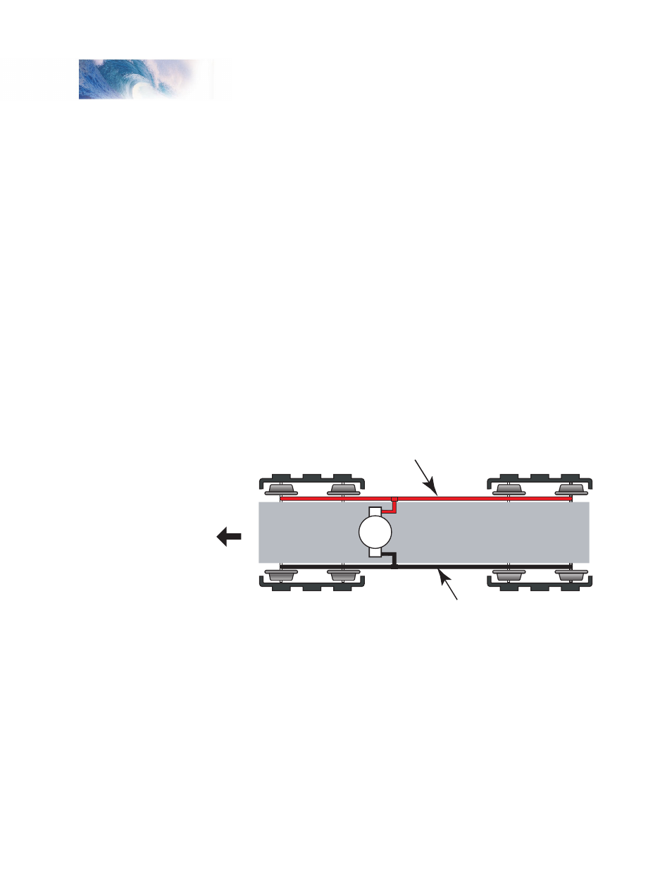
Figure 9 - Conventional DC Power Pickups
Disconnect all wires leading to both motor terminals. Note that some motor
brush connections are made using a spring contact to the chassis. In such
cases, it will be necessary to remove or modify the spring contact as well.
Be aware that some locomotives may make contact between the motor and
frame only when the body is reinstalled.
Installation
Left-hand Rail Pickup
Forward
Right-hand Rail Pickup
Motor