Installation, Step 8. install and wire the decoder, Track connections – SoundTraxx Tsunami Installation User Manual
Page 25: Motor connections, Non dcc-ready models)
Tsunami Installation Guide
Page 22
Tsunami Installation Guide
Page 22
Step 8. Install and Wire the Decoder
(Non DCC-Ready Models)
Begin by securing the decoder in place using double-sided foam tape.
Temporarily refit the tender or body shell to ensure that adequate clearance
still exists.
When wiring the decoder, trim all wires to reduce unnecessary lead length.
This will not only give your installation a neater appearance but also prevent
wires from interfering with the drive mechanism and getting pinched when
closing up the boiler or tender shell.
To ensure long-term reliability, solder all connections and insulate with heat-
shrink tubing such as SoundTraxx P.N. 810036.
Make your connections according to the Master Wiring Diagram and the
figures that follow.
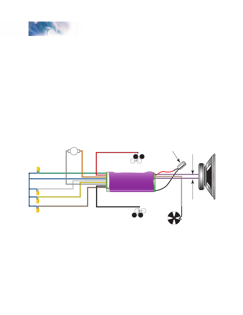
Figure 16 - Master Wiring Diagram
Track Connections
Connect the RED wire of the decoder’s wire harness to the right (engineer’s
side) track power pickup and the BLACK wire of the decoder’s wire harness
to the left track power pickup.
Motor Connections
Connect the ORANGE wire of the decoder’s wire harness to the motor’s (+)
terminal and the GRAY wire of the decoder’s wire harness to the motor’s (-)
terminal.
Installation
Speaker
Minus (-)
(Purple)
Headlight (White)
Backup Light (Yellow)
Function Common (Blue)
Function 5 Output (Brown)
Function 6 Output (Green)
Motor - (Gr
ay
)
M
ot
or
+
(
O
ra
ng
e)
Left-hand Rail Pickup (Black)
Right-hand Rail Pickup (Red)
Speaker
Plus (+)
(Purple)
Capacitor
Exhaust Cam
(Optional)
(Tan)