Installation – SoundTraxx Tsunami Installation User Manual
Page 23
Tsunami Installation Guide
Page 20
Tsunami Installation Guide
Page 20
Install the Synchronizer Disk
Carefully measure the diameter of your locomotive’s driver axle. Drill a hole
of the same diameter in the center of the synchronizer disk you plan to use.
Note: the thin disk material will be easier to drill if you temporarily adhere it
to a smooth wood block with a water soluble glue. The disk can be separated
from the block by soaking in water after the drilling operation is complete. Be
sure to use a sharp drill to get a clean burr-free hole.
Once the hole is drilled, check that there is still enough foil at the ‘hub’ to
connect all the spokes together. If not, you will need to use a synchronizer
disk with a larger hub.
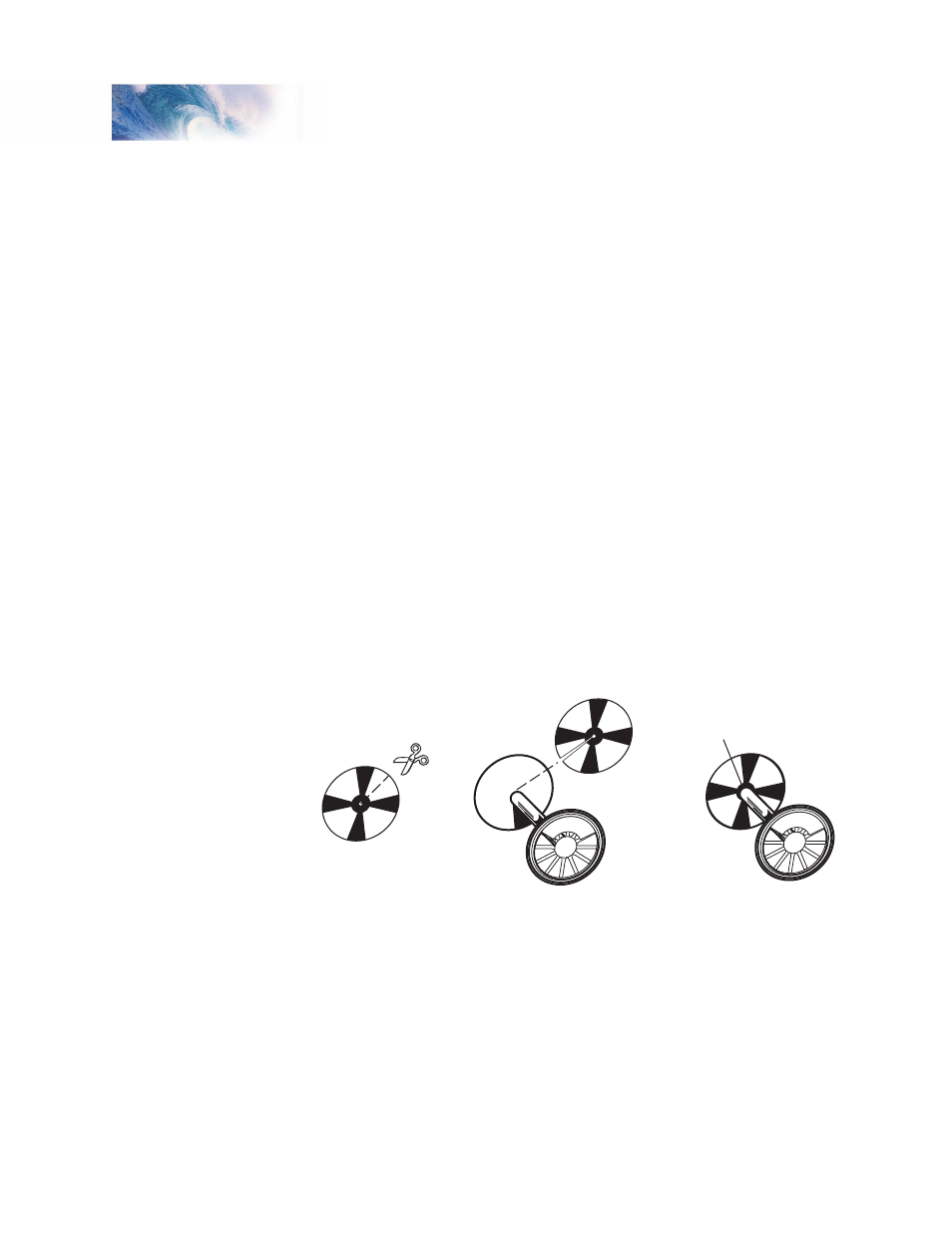
Cut the disk out with a sharp pair of scissors, and trim the disk diameter to
slightly less than the locomotive drive wheel diameter. This is important
as clearance will be needed to clear turnout frogs, guard rails, and other
trackwork features.
Using the scissors, make a single radial cut in the disk between the foil
spokes from the outer edge to the center hole. Slip the disk over the drive
axle with the insulated side facing against the drive wheel. Check for a
correct fit and make any needed adjustments. The disk should fit flush
against the drive wheel and there should be a close fit against the axle. Once
you are satisfied with the fit, glue the disk against the non-insulated drive
wheel with epoxy or contact cement. You will need to electrically connect the
synchronizer disk to the drive wheel axle. This is best done by soldering the
axle to the foil hub. Alternatively, you may use conductive paint to make the
connection.
Figure 13 - Synchronizer Disk Installation
Install the Cam Wiper
Using the spring wire supplied with the Exhaust Cam set, fabricate a contact
wiper. Bend the wire to match the pattern of Figure 14 using a pair of needle
nose pliers.
Solder the wiper to the small printed circuit board base as shown in Figure
14. Keep the spring wire as long as possible to provide flexibility. If the wire is
too short, it will rub against the synchronizer disk with excess force causing
premature wear and possible binding.
Installation
1. Cut and trim
disk to fit
2. Glue disk to
uninsulated
driver
3. Solder disk
hub to axle