Installation, Exhaust cam connections – SoundTraxx Tsunami Installation User Manual
Page 29
Tsunami Installation Guide
Page 26
Tsunami Installation Guide
Page 26
4. To wire the Function 6 output, connect one end of the bulb to the
decoder’s GREEN wire. Wire the other bulb lead to the decoder’s BLUE
wire.
Any outputs not used can be left disconnected, but you should cut off and
insulate the ends of the wires so they do not come in contact with locomotive
or locomotive wiring.
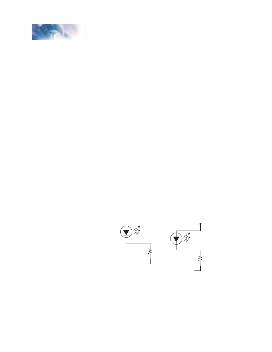
Using LEDs
Tsunami decoders may be used with LEDs, which also require a resistor to
be wired in series, typically about 680-ohms, 1/4W. Unlike lightbulbs, LEDs
are sensitive to polarity. The minus (-) cathode end of the LED (the shorter of
the two leads) is connected to the function output and the plus (+) anode end
is connected to the decoder’s BLUE (function common) wire.
1. To wire the Headlight, connect the cathode end of the LED to the one
lead of the resistor. Wire the other resistor lead to the decoder’s WHITE
wire. Wire the anode LED lead to the decoder’s BLUE wire.
2. To wire the Backup light, connect the cathode end of the LED to one lead
of the resistor. Wire the other resistor lead to the decoder’s YELLOW
wire. Wire the anode LED lead to the decoder’s BLUE wire.
If you use Functions 5 and 6 for lighting effects:
3. To wire the Function 5 output, connect the cathode end of the LED to
one lead of the resistor. Wire the other resistor lead to the decoder’s
BROWN wire. Wire the anode LED lead to the decoder’s BLUE wire.
4. To wire the Function 6 output, connect the cathode end of the LED to
one lead of the resistor. Wire the other resistor lead to the decoder’s
GREEN. Wire the anode LED lead to the decoder’s BLUE wire.
Figure 23 - Wiring the Decoder for LED Lamps
Exhaust Cam Connections
(steam only)
Connect the TAN wire from the 3-pin Speaker/Cam harness of the DSD to
the exhaust cam wiper switch. The decoder is factory-programmed to operate
using the Auto-Exhaust feature. If you wish to use an exhaust cam, you must
enable the cam-synchronized exhaust by setting CV 112 to 128.
Installation
FUNCTION COMMON
BLUE
Forward
Lamp
Reverse
Lamp
680 ohm
Resistor
WHITE
YELLOW
Cathode (-)
680 ohm
Resistor
Cathode (-)
LEDS