Installation, Step 3. plan the installation – SoundTraxx Tsunami Installation User Manual
Page 11
Tsunami Installation Guide
Page 8
Tsunami Installation Guide
Page 8
Step 3. Plan the Installation
You should give some thought to where the installation of the various DSD
components will be within the locomotive before you get started. Provide
ventilation for the decoder if possible, mounting the decoder so that some
airflow can occur. Also, mount the decoder away from other heat sources,
such as the motor or lamps to reduce the chance of overheating. If you can,
mount the decoder so that the ‘flat’ side is against a metal chassis or weight.
This will further help to dissipate heat. Always, always provide a proper baffle
(enclosure) for the speaker. Lack of a speaker baffle is the leading cause
of poor sound quality or low volume. Finally, make sure to use the largest
speaker that you can fit, as a bigger speaker will provide more volume and
deeper bass.
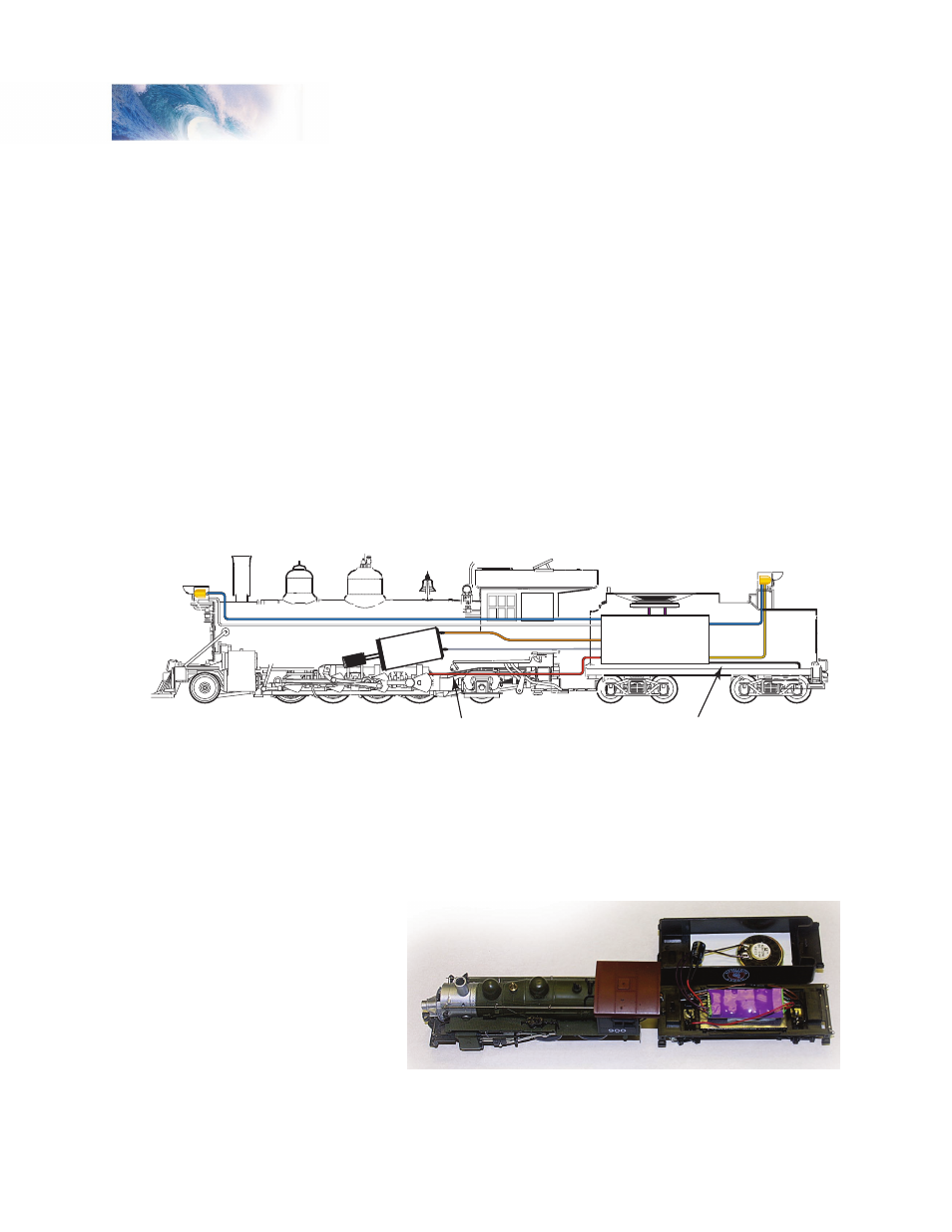
Figure 2 shows a typical Tsunami installation in a die-cast locomotive.
Following as many of the guidelines above as possible, we’ve mounted the
flat side of the decoder against the tender shell to help dissipate some heat.
The speaker is mounted up under the coal load, and the decoder is not
mounted near the motor or lamps.
Figure 2 - Typical Steam Sound Installation
In Figure 3, the speaker is mounted on a deck plate fabricated from sheet
styrene pointing up through the coal load. The tender shell acts as a baffle
for the speaker. The plastic coal load can be perforated with small holes
made with
a pin vise
or hand
drill. The
decoder is
mounted to
the weight
on the
floor of the
tender.
Installation
Backup Light
Right Rail Pickup
usually connects
to locomotive frame
Headlight
Speaker
Left Rail Pickup
usually connects
to tender frame
Blue
White
Motor (+) Lead
Motor (-) Lead
Black
Yellow
Purple
Blue
Orange
Gray
Red
Digital
Sound
Decoder
Figure 3 - A typical speaker installation using the tender as
the speaker enclosure.