Smithy GN1300 User Manual
Page 69
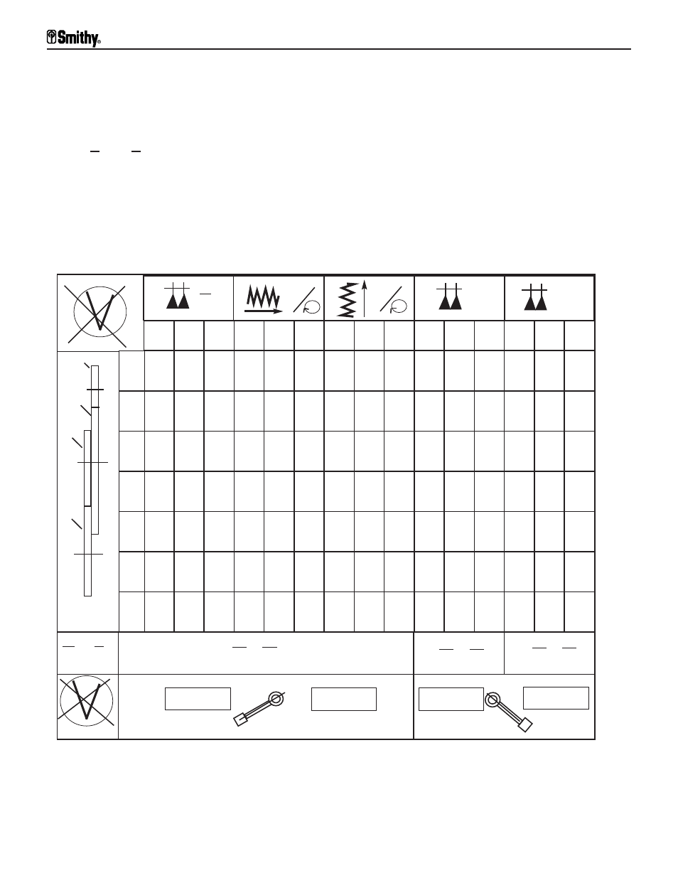
Below the symbol is a representation of the feed gears, A, B, C, and D on the
gear quadrant. These gears are located inside the pulley box. Immediately to
the right of the gear symbols are the numbers 1 through 7, which refer to the
position of the powerfeed selection lever (1-7) on the feed transmission.
Below the gear symbols is the location guide for the gear numbers
which are stamped on the face of the gears. This formula refers to
which gear number belongs in which location in order to move the
carriage or table for threading and powerfeeding.
A
C
B D
X
1”
N
in
in
in
in
A
B
C
D
7
14
28 0.125 0.250 0.500 0.039 0.079 0.157 0.35 0.70
1.75 3.50
8
16
32 0.109 0.218 0.437 0.034 0.069 0.138 0.40 0.80
1.00 2.00 4.00
9
18
36 0.097 0.194 0.388 0.031 0.061 0.122 0.45
4.50
10
20
40 0.087 0.175 0.349 0.028 0.055 0.110 0.50 1.00
1.25 2.50 5.00
11
22
44 0.079 0.159 0.317 0.025 0.050 0.100
2.75 5.50
12
24
48 0.073 0.146 0.291 0.023 0.046 0.092 0.60
1.50
(0.75)
3.00 6.00
13
26
52 0.067 0.134 0.269 0.021 0.042 0.085
3.25 6.50
II
III
III
II
I
III
II
I
III
II
I
III
II
I
X
30
60
66 60
X
33
63
80 60
X
(33)66
63
64 60
X
1
2
3
4
5
6
7
A
C
B D
I
INCH
METRIC
INCH
METRIC
Header Section 1 Section 2 Section 3
Section 4 Section 5
Figure 8.6 Feed Rate Chart
Granite 1300 Series Operator’s Manual
8-6
For Assistance: Call Toll Free 1-800-476-4849