Sloan 10xx Slimline Bedpen Washer w/ Royal Flushometer User Manual
Page 3
3
With the exception of Control Stop Inlet, DO NOT use pipe sealant or plumbing
grease on any valve component or coupling!
!!! IMPORTANT !!!
Protect the chrome or special finish of Sloan Flushometers — DO NOT USE
toothed tools to install or service these valves. Use a Sloan A-50 Super-
Wrench™, Sloan A-109 Plier Wrench or smooth jawed spud wrench to secure
all couplings. Also see “Care and Cleaning” section of this manual.
!!! IMPORTANT !!!
This product contains mechanical and/or electrical components that are
subject to normal wear. These components should be checked on a regular
basis and replaced as needed to maintain the valve’s performance.
!!! IMPORTANT !!!
If you have questions about how to install your Sloan Flushometer, consult your
local Sloan Representative or call Sloan Installation Engineering Department at:
1-888-SLOAN-14 (1-888-756-2614) OR 1-847-233-2016
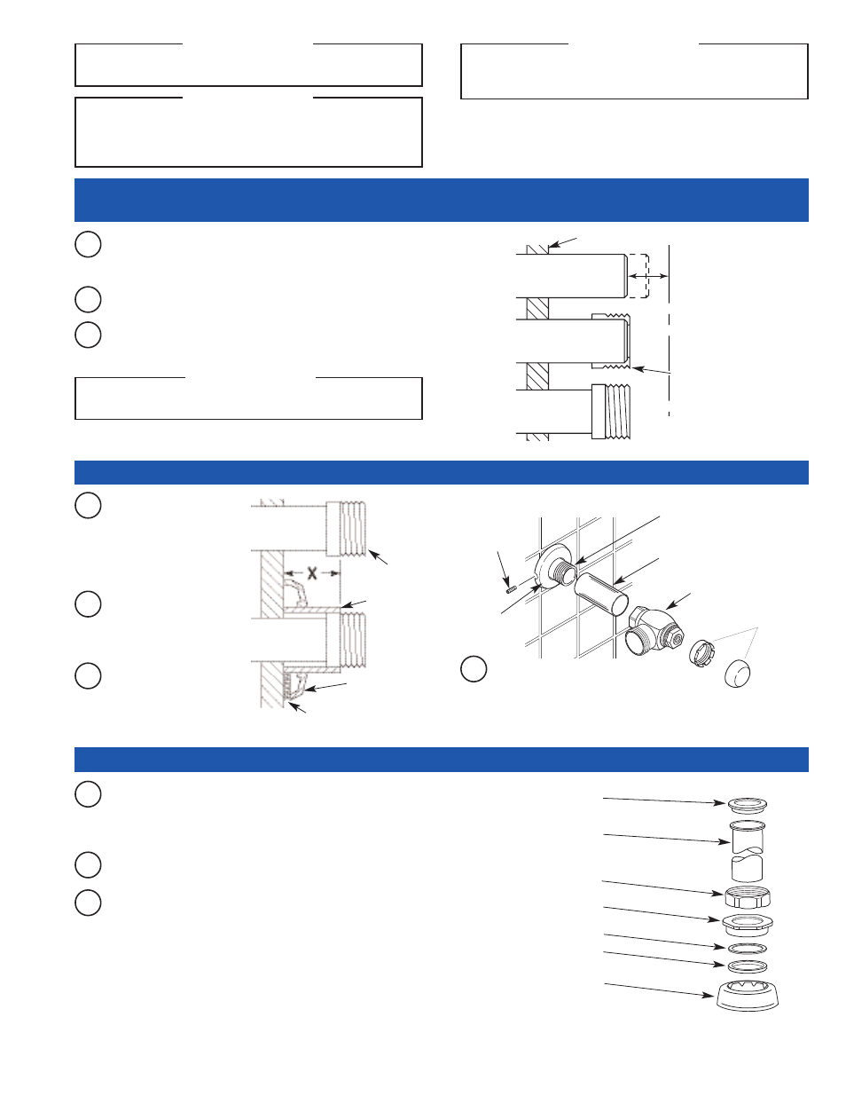
A
Measure from finished wall to C/L of Fixture Spud. Cut pipe 1¼"
(32 mm) shorter than this measurement. Chamfer O.D. and I.D. of
water supply pipe.
WATER SUPPLY PIPE
FINISHED WALL
1-1/4”
(32 mm)
C/L OF
FIXTURE
SPUD
SWEAT
SOLDER
ADAPTER
B
Slide Threaded Adapter fully onto pipe.
C
Sweat solder the Adapter to pipe.
With the exception of Control Stop Inlet, DO NOT use pipe sealant or plumbing
grease on any valve component or coupling!
!!! IMPORTANT !!!
Slide the diverter valve coupling nut, spud coupling, nylon slip
gasket, rubber gasket and spud flange over the flanged outlet tube
and insert tube into fixture spud. Place tube gasket on top of
flanged outlet tube as shown.
A
Hand tighten spud coupling onto fixture spud.
B
Place tube gasket on top of flanged outlet tube as shown.
C
TUBE GASKET
FLANGED OUTLET TUBE
DIVERTER VALVE COUPLING NUT
SPUD COUPLING
NYLON SLIP GASKET
RUBBER GASKET
SPUD FLANGE
Thread Control Stop onto
pipe. Tighten with a
wrench.
BAK-CHEK
®
CONTROL STOP
COVER TUBE
IRON PIPE NIPPLE OR
COPPER PIPE WITH SWEAT
SOLDER ADAPTER
SET SCREW
SUPPLY
FLANGE
WATER
SUPPLY PIPE
SWEAT SOLDER
ADAPTER
COVER TUBE
WALL
FLANGE
SET SCREW
A
Measure from finished
wall to first thread of
Adapter or threaded
supply pipe (dimension
“X”). Cut Cover Tube to
this length.
B
Slide Cover Tube over
pipe. Slide Wall Flange
over Cover Tube until
against wall.
C
Tighten Set Screw with a 1/16”
hex wrench. DO NOT install
Vandal Resistant Stop Cap or
Plug at this time.
D
VANDAL
RESISTANT
STOP CAP
1 - INSTALL OPTIONAL SWEAT SOLDER ADAPTER (ONLY IF YOUR SUPPLY PIPE DOES
NOT HAVE A MALE THREAD)
2 - INSTALL COVER TUBE, WALL FLANGE, AND CONTROL STOP TO SUPPLY PIPE
3 - INSTALL FLANGED OUTLET TUBE (RETROFIT APPLICATIONS START HERE)
- 11xx Slimline Bedpen Washer w/ Royal Flushometer 100 Slimline Bedpen Washer w/ Royal Flushometer 105 Slimline Bedpen Washer w/ Royal Flushometer 110 Slimline Bedpen Washer w/ Royal Flushometer 115 Slimline Bedpen Washer w/ Royal Flushometer 120 Slimline Bedpen Washer w/ Royal Flushometer 125 Slimline Bedpen Washer w/ Royal Flushometer 130 Slimline Bedpen Washer w/ Royal Flushometer 135 Slimline Bedpen Washer w/ Royal Flushometer