Sloan 110 Sloan Exposed Flushometer User Manual
Page 3
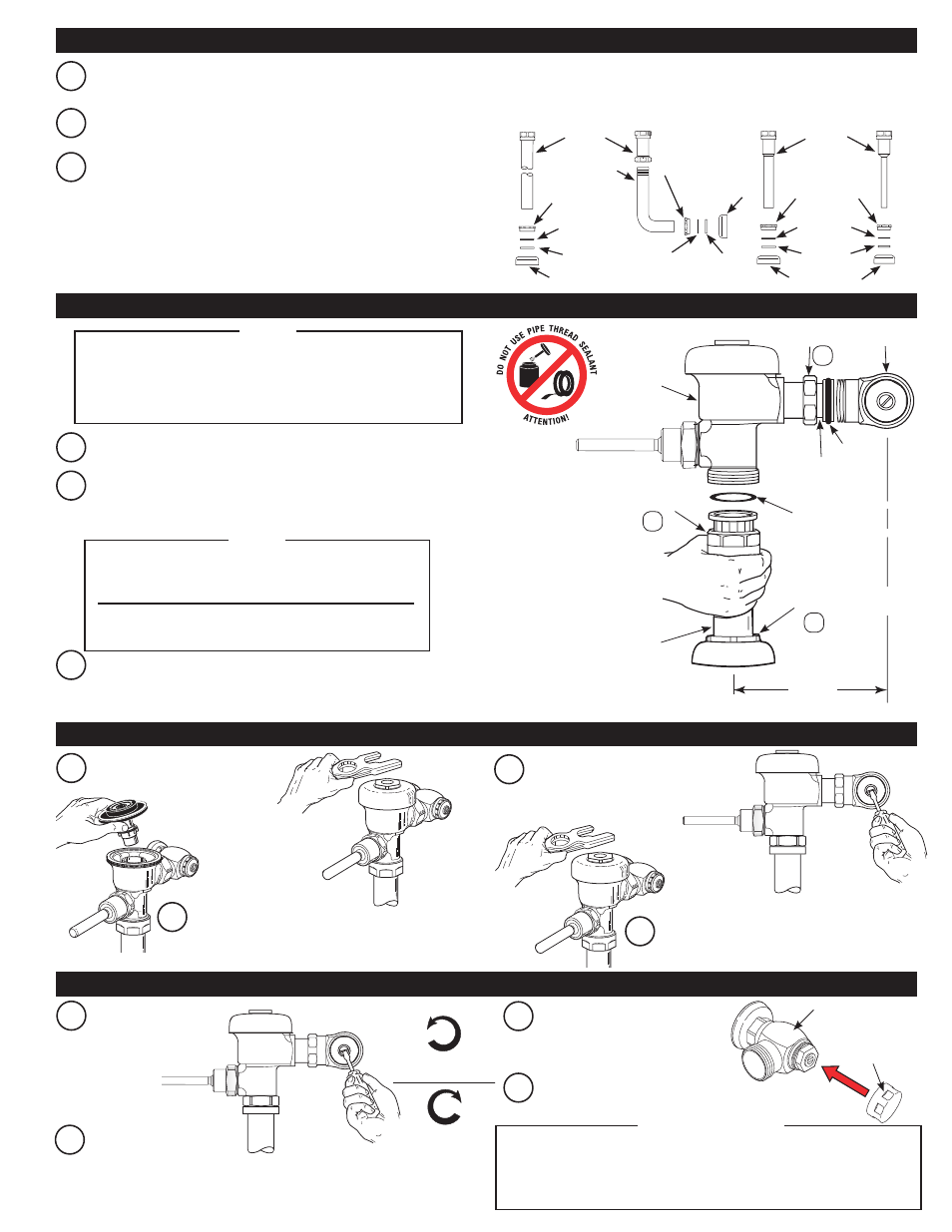
TURN COUNTER-
CLOCKWISE TO OPEN
TURN CLOCKWISE
TO CLOSE
CONTROL STOP CAP
H-700-A BAK CHEK
®
CONTROL STOP
D
Install vandal resistant control
stop cap onto control stop.
VACUUM
BREAKER
TUBE
SPUD COUPLING
NYLON SLIP
GASKET
RUBBER
GASKET
SPUD FLANGE
A
Slide spud coupling, nylon slip gasket, rubber gasket and spud
flange over vacuum breaker tube.
B
Insert tube into fixture spud.
C
Hand tighten spud coupling onto fixture spud.
VACUUM
BREAKER
TUBE
SPUD COUPLING
NYLON SLIP
GASKET
RUBBER
GASKET
SPUD FLANGE
SPUD COUPLING
NYLON
SLIP
GASKET
RUBBER
GASKET
SPUD FLANGE
A
Make sure control stop is CLOSED
and remove flushometer outer cover.
C
Reinstall outside and inside cover wrench
tight. Open control stop to flush supply
line. Close control stop and remove
outside and inside cover.
B
Remove inside cover and lift out inside parts
assembly.
D
Reinstall inside parts assembly, inside
cover and outside cover wrench tight.
C
Align flushometer body and securely tighten first the tailpiece
coupling
(1), then the vacuum breaker coupling (2), and finally the
spud coupling
(3). Use a wrench to tighten these couplings in the
order shown.
B
Align flushometer directly above the vacuum breaker flush
connection by sliding the flushometer Body IN or OUT as needed.
Tighten vacuum breaker coupling by hand.
A
Lubricate tailpiece o-ring with water. Insert adjustable tailpiece into
control stop. Tighten tailpiece coupling by hand.
Maximum adjustment of the Sloan Adjustable Tailpiece is
1/2” (13 mm) IN or OUT from the standard 4-3/4” (121 mm)
(centerline of Flushometer to centerline of Control Stop).
If roughing-in measurement exceeds 5-1/4” (133 mm),
consult factory for longer tailpiece.
NOTE
MODELS 110/111,
113, 114, 115,
116, 117
MODELS 120, 121, 122
MODEL 180
MODEL 186
ELBOW FLUSH
CONNECTION
B
Activate flushometer.
C
Adjust control stop after each
flush until the rate of flow
delivered properly cleanses the
fixture.
Sloan’s flushometers are engineered for quiet operation. Excessive water flow
creates noise, while too little water flow may not satisfy the needs of the fixture.
Proper adjustment is made when plumbing fixture is cleansed after each flush
without splashing water out from the lip AND a quiet flushing cycle is achieved.
!!! IMPORTANT !!!
TAILPIECE
COUPLING
CONTROL
STOP
1
FLUSHOMETER
BODY
VACUUM
BREAKER
COUPLING
2
ADJUSTABLE
TAILPIECE
O-RING
G-44
FRICTION
RING
SPUD
COUPLING
3
C/L
FIXTURE
C/L
SUPPLY
VACUUM
BREAKER
FLUSH
CONNECTION
4-3/4”
(121 mm)
±1/2”
(13 mm)
3 - INSTALL VACUUM BREAKER FLUSH CONNECTION
4 - INSTALL FLUSHOMETER
5 - FLUSH OUT SUPPLY LINE
6 - ADJUST CONTROL STOP AND INSTALL VANDAL RESISTANT STOP CAP
A
Open control stop
COUNTERCLOCKWISE
one FULL turn from
closed position.
For high efficiency urinal flushometers (0.5, 0.25 and 0.125 gpf),
it is necessary to first insert the flow control component into the
tailpiece assembly. See the H1015A flow control kit and separate
instructions for details on how to install.
NOTE
- 111 Sloan Exposed Flushometer 113 Sloan Exposed Flushometer 115 Sloan Exposed Flushometer 116 Sloan Exposed Flushometer 117 Sloan Exposed Flushometer 180 Sloan Exposed Flushometer 186 Sloan Exposed Flushometer 120 Sloan Exposed Flushometer 121 Sloan Exposed Flushometer 122 Sloan Exposed Flushometer 111 UPPERCUT Flushometer 113 UPPERCUT Flushometer 115 UPPERCUT Flushometer 116 UPPERCUT Flushometer 120 UPPERCUT Flushometer 601 Prison Flushometer 603 Prison Flushometer 611 Prison Flushometer 681 Prison Flushometer 609 Prison Flushometer 613 Prison Flushometer 9603 Prison Flushometer 9609 Prison Flushometer 9613 Prison Flushometer