Rough-in – Sloan 110 Sloan Exposed Flushometer User Manual
Page 2
A
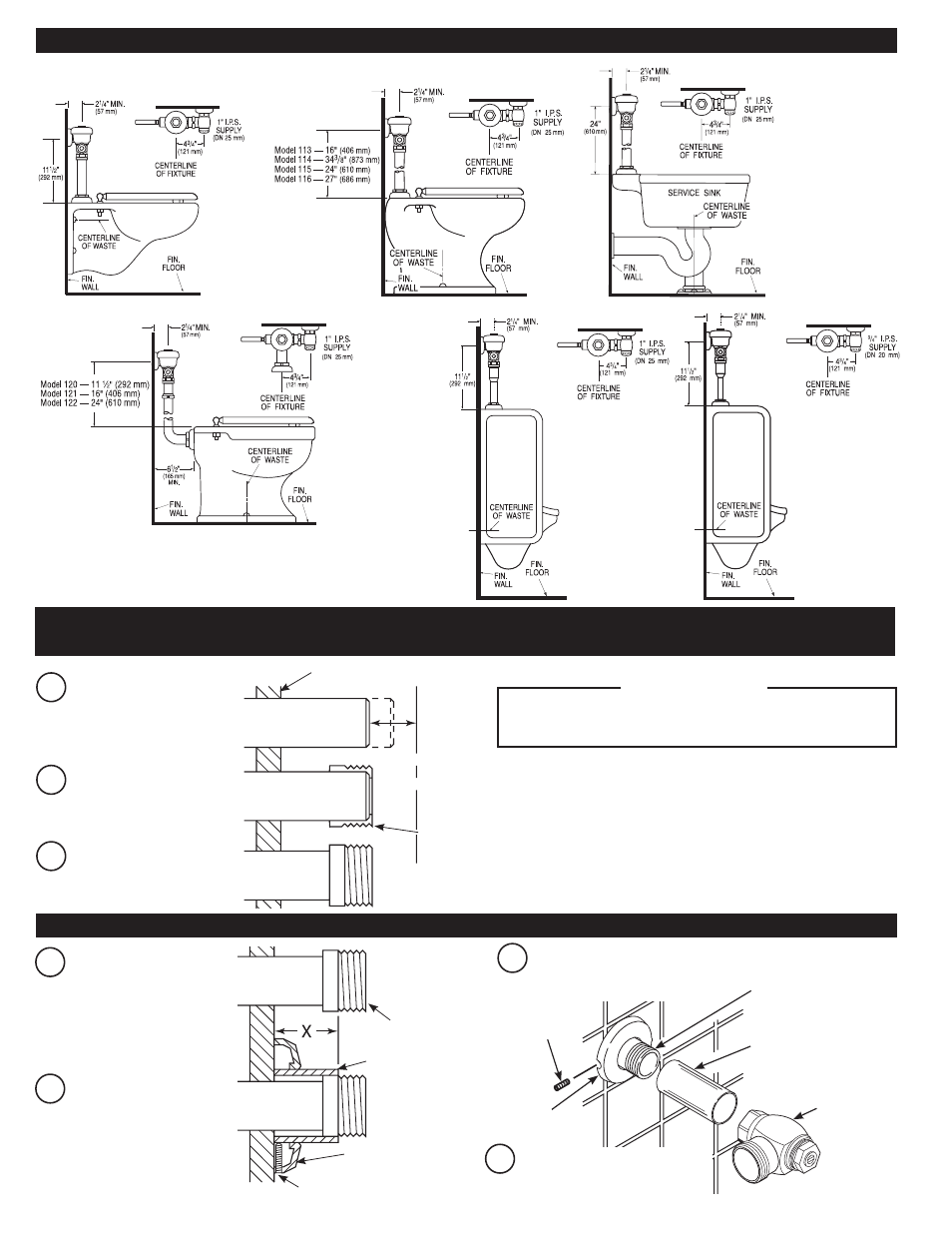
Measure from finished wall to
C/L of fixture spud. Cut pipe
1⁄” (32 mm) shorter than this
measurement. Chamfer O.D.
and I.D. of water supply pipe.
WATER SUPPLY PIPE
FINISHED WALL
1-1/4”
(32 mm)
C/L OF
FIXTURE
SPUD
SWEAT
SOLDER
ADAPTER
B
Slide threaded adapter fully
onto pipe.
C
Sweat solder the adapter to
pipe.
BAK-CHEK
®
CONTROL STOP
COVER TUBE
IRON PIPE NIPPLE OR
COPPER PIPE WITH SWEAT
SOLDER ADAPTER
SET SCREW
SUPPLY
FLANGE
WATER
SUPPLY PIPE
SWEAT
SOLDER ADAPTER
COVER TUBE
WALL
FLANGE
SET SCREW
A
Measure from finished wall
to first thread of adapter
or threaded supply pipe
(dimension “X”). Cut cover
tube to this length.
B
Slide cover tube over pipe.
Slide wall flange over cover
tube until against wall.
Thread control stop onto pipe.
Tighten with a wrench.
C
Tighten Set Screw with a 1/16”
hex wrench. DO NOT install Vandal
Resistant Stop Cap at this time.
D
WITH THE EXCEPTION OF CONTROL STOP INLET, DO NOT
USE PIPE SEALANT OR PLUMBING GREASE ON ANY VALVE
COMPONENT OR COUPLING!
!!! IMPORTANT !!!
1 - INSTALL OPTIONAL SWEAT SOLDER ADAPTER (ONLY IF YOUR SUPPLY PIPE DOES NOT
HAVE A MALE THREAD)
2 - INSTALL COVER TUBE, WALL FLANGE AND CONTROL STOP TO SUPPLY PIPE
MODEL 110/111
MODELS 113,
114, 115 & 116
MODEL 117
MODELS 120, 121, & 122
MODEL 180
MODEL 186
NOTE: Requires 1”
I.P.S. (DN 25 mm)
Supply.
IMPORTANT NOTES:
• When mounted on an ADA accessible bowl, the rough-in to the supply inlet should be no higher
than 37fi” or the handle will exceed maximum height allowances under ADA guidelines.
• New ADAAG Guidelines allow for Split or Offset Grab Bars, check with local authorities or
reference section 604.5.2 of ADAAG.
ROUGH-IN
- 111 Sloan Exposed Flushometer 113 Sloan Exposed Flushometer 115 Sloan Exposed Flushometer 116 Sloan Exposed Flushometer 117 Sloan Exposed Flushometer 180 Sloan Exposed Flushometer 186 Sloan Exposed Flushometer 120 Sloan Exposed Flushometer 121 Sloan Exposed Flushometer 122 Sloan Exposed Flushometer 111 UPPERCUT Flushometer 113 UPPERCUT Flushometer 115 UPPERCUT Flushometer 116 UPPERCUT Flushometer 120 UPPERCUT Flushometer 601 Prison Flushometer 603 Prison Flushometer 611 Prison Flushometer 681 Prison Flushometer 609 Prison Flushometer 613 Prison Flushometer 9603 Prison Flushometer 9609 Prison Flushometer 9613 Prison Flushometer