Sierra Video Pro XL Series 8 User Manual
Page 37
OPERATION
31
Control via 9-pin Connectors
The 9-pin connectors allow you to control the routing switcher via an external computer. On some
switcher models, the serial port can be changed internally for RS422 configuration (RS232 is
factory configuration).
Each routing switcher model has one port and it is labeled on the back panel as “RS232/422
Control” (refer also to the illustrations of back panels shown in Chapter 1):
Connection to the RS-232/422 port is made using a standard 9 pin (pin to pin) cable.
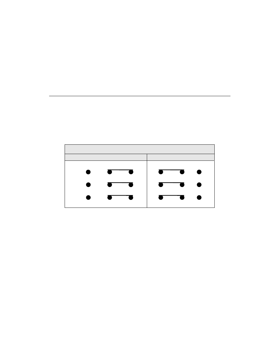
Conversion to RS-422:
To convert the RS-232 serial control to RS-422, remove top cover of router. Locate the processor
board on the rear of the front panel. The jumpers are located in approximately the center of the
processor PCB.The jumpers are labeled JP1, JP2, and JP3.
Jumper positions are as follows:
Pro Series 12 & 8 Switchers
RS-232
RS-422
1 2 3
JP1
JP2
JP3
1 2 3
Control via Ethernet
The matrix switches may be controlled via Ethernet using the Host Protocol. To control to the
matrix switcher establish a TCP/IP connection to the IP addresses of the routing matrix using port
number 10001. A communications program such as Hyper Access can be used to establish this
connection. Once the connection is established, sending the command **!! should cause the
routing matrix to return ** OK !!. This connection supports the entire Sierra Video Host protocol
command set.
- Pro XL Series 12 Shasta HD 88 HD Shasta HD 88 SDI 1601 Series HD/SDI Shasta HD Scanning Routing Switchers 1602 Series HD/SDI Shasta HD Routing Switchers 1602 Series HD/SDI Shasta HD Scanning Routing Switchers 1601 Series HD/SDI Dual Output Shasta HD Routing Switchers 1616 Series HD/SDI 3G Shasta HD Routing Switcher Alta Pro Series Tahoe 3232CAA Tahoe 32128V Lassen XL Series VS Lassen XL Series DE Lassen XL Series HD Lassen XL Series SDI Tahoe 3264VAA Tahoe Series 48 Tahoe Series 16 Tahoe Series 20 Shasta 88D Shasta 88E Shasta 1601D Shasta 1616D Tahoe Series 32 Shasta Series 16 Shasta Series 32 Pro XL Series 16 Pro XL Series 32 NLE Pro Series 8 Pro Series 12 Pro Series 16