Water level sensor maintenance – Scotsman 600 Eclipse User Manual
Page 40
Water Level Sensor Maintenance
In most cases the water level sensor will not
require maintenance. However, if the area where
the ice making section is located is dusty or there
is a high concentration of minerals in the water, the
infrared emitter and detector lenses inside the
sensor may need to be wiped off.
1. Remove front panel.
2. Push and hold the Off button until the machine
stops.
3. Unplug sensor wire harness from sensor.
4. Remove two screws holding dust cover to
sensor.
5. Wipe the four lenses with a cotton swap soaked
in potable water.
6. Return the dust cover to its original position,
secure with the original screws.
7. Reconnect wire harness.
8. Push and release the Freeze button.
9. Return the front panel to its normal position.
Water Level Sensor Diagnosis
Tools Needed: Digital voltmeter that can read DC
Note: Ambient light can affect this test. Shade the
sensor if needed.
1. Unplug water sensor harness from controller
(connection #2).
2. Confirm that the power to the machine is ON
and that there is at least one light on the board that
is glowing. If not, check the transformer.
3. Set the voltmeter to DC and use a scale low
enough to measure less than 40 Volts.
4. Measure the voltage between the top and the
bottom pins on the controller at connection #2 (the
bottom is ground or negative).
·
Harness unplugged - .5 to 2 VDC
Eclipse
ä 600, 800, 1000
April 2002
Page 40
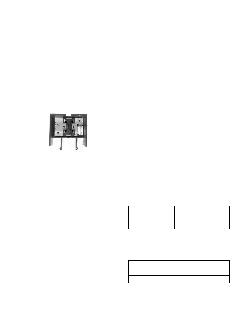
Water Level Sensor, Dust Cover Removed
Clean
Lenses
Clean
Lenses
If it is much less than that, there is something
wrong with either the power supply to the controller
or the controller itself. If the voltage measures
correctly proceed to the next step.
5. Reconnect the harness. Be SURE it is on
properly and has a good connection. To confirm,
unplug the harness from the water sensor and
redo step #4 at the end of the harness. Then plug
the harness back onto the sensor.
Harness Connected Voltage (DC)
6. At the controller, measure the voltage between
the top and bottom pins on connection #2. This
should be between the ranges in the table below. If
it outside this range there is a problem in the
sensor and it should be changed out. If it is within
this range, proceed to the next step.
7. Place negative voltmeter probe on the bottom
terminal (yellow wire). Place the other on the one
just above it (terminate freeze sender - white wire).
Move the float stem/stick up and down and note
the voltage changes. There should be a significant
change between when it is blocked to when it is
not blocked. If there is NO change, the sensor
may be dirty or has failed. Remove the dust cover
from the sensor to clean it.
Note: The sensor must be properly reassembled.
When looking at the terminals of the sensor, they
must be in the lower right corner. If they are in the
upper left remove the sensor’s dust cover and
reverse the board. Later models have an UP arrow
on the right side of the circuit board.
Yellow (bottom)
White - Blocked
about 5 VDC
White - Unblocked
less than when blocked
8. With the voltmeter probe still on the bottom
terminal (connection #2), place the other probe on
the second pin from the top (sump full sender - red
wire). Move the float stick up & down, changes in
voltage should be the same as in step 7.
Yellow (bottom)
Red - Blocked
about 5 VDC
Red - Unblocked
less than when blocked
9. If all voltages check out, there is nothing wrong
with the sensor or the voltage it receives from the
controller.