Remko cmf / cmt, Terminal block/legend – REMKO CMF-120-1P User Manual
Page 46
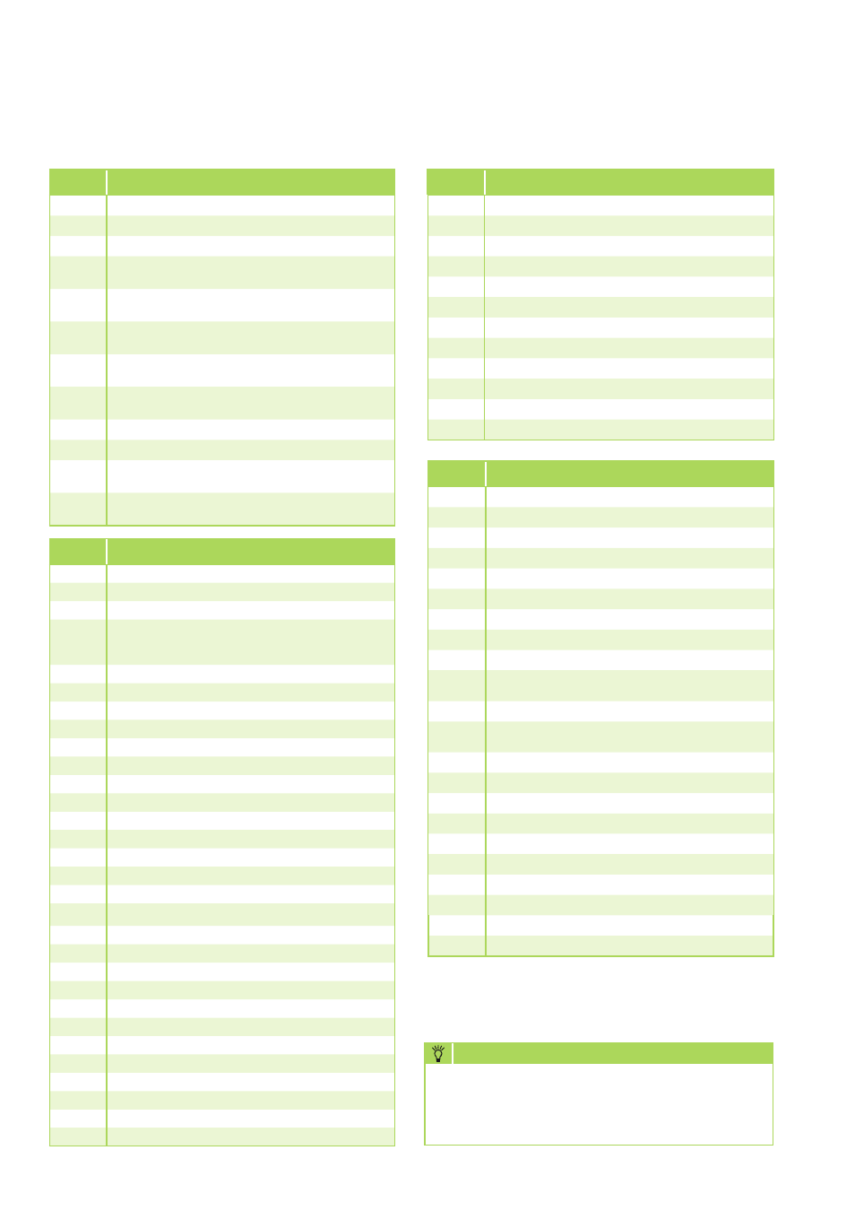
REMKO CMF / CMT
Terminal block/legend
Termi-
nal
Connection layout (low-voltage sensor)
X3.
Earth
X3.1
CAN-Bus H
X3.2
CAN-Bus +
X3.3
CAN-Bus L
X3.4
CAN-Bus -
X3.5
eBus - (nominal output in % above 0-10 V -signal)
X3.6
eBus + (nominal output in % above 0-10 V -signal)
X3.7
F17 Return sensor (cooling-control sensor)
X3.8
F15 sensor (option: flow-volume regulator)
X3.9
F14 Solar-collector or Solid-fuel-boiler sensor
(pt 1000)
X3.10
(not connected)
X3.11
F12 Lower buffer storage
(reference sensor, solar or solid-fuel boiler)
X3.12
F11 Inlet sensor, heat pump or heating-circuit 1
X3.13
F9 External sensor
X3.14
F8 Collector sensor, common inlet (heating-control sensor)
X3.15
F6 Warm-water-storage sensor
X3.16
F5 Inlet sensor, heating-circuit 2 (mixing circuit)
X3.17
F3 (not connected)
X3.18
F2 (not connected)
X3.19
F1 (not connected)
X3.20
Liquid-temperature sensor, cooling circuit
X3.21
Undercooling temperature, cooling circuit
The connection terminals X1.4 through x1.9, as
well as X2.15 and X2.18 are available only when
the electric booster heater is installed or when it
is standard equipment (CMT)
NOTE
Termi-
nal
Connection layout (outputs)
X2.1
Control cable, outdoor- and indoor module - S1
X2.2
Control cable, outdoor- and indoor module - S2
X2.3
Control cable, outdoor- and indoor module - S3
X2.4
Enable 2. Heat generator (common contact,
optionally potential free or 230 V feed over the
bridge at X2.19)
X2.5
Enable 2. Heat source (open)
X2.6
Enable 2. Heat source (closed)
X.2.7
Switching valve 2. Heat generator - OPEN
X2.8
Switching valve 2. Heat generator - N
X2.9
Switching valve 2. Heat generator - OFF
X2.10
Mixer, heating circuit 2 - OPEN
X2.11
Mixer, heating circuit 2 - N
X2.12
Mixer, heating circuit 2 - CLOSED
X2.13
Power plant enable/disable
X2.14
Power plant enable/disable
X2.15
Contactor K6-A1/L‘, 6 kW elec. booster heater
X2.16
Flow monitor
X2.17
Flow monitor
X2.18
Contactor K6 and K8-A2/N1.2, elec. booster
heater
X2.19
Live phase - L'
X2.20
Live phase - L'
X2.21
Live phase - L'
X2.22
Circulation pump, heating circuit 1 - L
X2.23
Circulation pump, heating circuit 1 - N
X2.24
Circulation pump, heating circuit 1 - PE
X2.25
Circulation pump, heating circuit 2 - L
X2.26
Circulation pump, heating circuit 2 - N
X2.27
Circulation pump, heating circuit 2 - PE
X2.28
Switching valve, warm water L" - black
X2.29
Switching valve, warm water N - grey
X2.30
PE
Termi-
nal
Connection layout (supply)
X1.1
Power supply, indoor module - L
X1.2
Power supply, indoor module - N
X1.3
Power supply, indoor module - PE
X1.4
Power supply, E-heater - L1
(optional for CMF Series).
X1.5
Power supply, E-heater - N
(optional for CMF Series).
X1.6
Power supply, E-heater - PE
(optional for CMF Series).
X1.7
Power supply, E-heater - L1
(optional for CMF Series).
X1.8
Power supply, E-heater - L1
(optional for CMF Series).
X1.9
PE
X1.10
PE
X1.11
Power supply, E-heater - N
(optional for CMF Series).
X1.12
Power supply, E-heater - N1
(optional for CMF Series).
Termi-
nal
Connection layout (outputs) continuation
X2.31
Switching valve, cooling L" - black
X2.32
Switching valve, cooling N - grey
X2.33
PE
X2.34
Circulation pump, cooling - L
X2.35
Circulation pump, cooling - N
X2.36
Circulation pump - PE
X2.37
Circulation- or solar pump - L
X2.38
Circulation- or solar pump - N
X2.39
Circulation- or solar pump - PE
X2.40
Charge pump, indoor module - L
X2.41
Charge pump, indoor module - N
X2.42
Charge pump, indoor module - PE
46