Connection diagram, terminal configuration – REMKO CMF-120-1P User Manual
Page 37
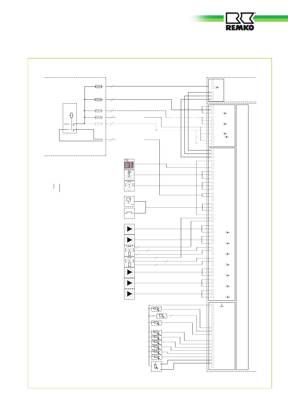
Connection diagram, terminal configuration
Outdoor
unit
Indoor unit
Terminal block X1
Terminal block X2
Terminal block X3
On-site
sub-distribution
connection layout CMF/CMT 120 and
160-1P (1-phase outdoor units)
Observe the technical
requir
ements of the local
power company
Outdoor-module supply
Inndoor-module supply
E-heater supply
Power enable/disable (230 V
~
)
e.g.:NYM-I 3x1.5mm
2
Normally-closed switch
Normally-open switch
enable 2. heat source *)
(4-way) switching valve
2. heat source
3-way mixer HK2
Circulation pump HK 1
Circulation pump HK 2 Mixer circuit
Switching valve Hot-water usage
Switching valve, cooling
blu
blk
blu
blk
Circulation pump, cooling
Charging pump, indoor
module
Circulation pump, solar or circulation or
Solid-fuel combustion vessel
F 17 Return, heat pump
F 14 Solar collector or Solid-fuel-boiler sensor
F 12 Reference sensor, lower buffer storage
F 11 Inlet, heat pump
F 9 Outdoor temperature
F 8 T-collector (com. inlet)
F 6 Warm-water storage
F 5 Inlet HK2 (mixing circuit
Relay switch
Inputs/outputs
(Merlin I/O circuit board)
Flow monitor **)
or
jumper ***)
blu
white
M
Analogue remote control with room sensor
F 15 Flow rate transmitter ***)
*)
Th
ere
is
an
o
ptio
n f
or
th
e b
oile
r e
na
blin
g t
o o
ccu
r w
ith
ou
t v
olt
ag
e o
r
w
ith
2
30
V
(p
ha
se
-b
rid
ge
d f
ro
m
X
2.1
9)
w
ith
w
hic
h a
n
orm
ally
-clo
se
d s
w
itc
h o
r a
n
orm
ally
-o
pe
n s
w
itc
h c
an
b
e e
m
plo
ye
d.
**
)
O
nly
in
a s
et-
up
w
ith
ou
t h
ot
w
ate
r m
ete
rs
**
*)
O
nly
in
a s
et-
up
w
ith
h
ot
w
ate
r m
ete
rs
e.g.: 3xNYM-I 3x1.5mm
2
e.g.: 3xNYM-I 3x1.5mm
2
e.g.: 3xNYM-I 3x1.5mm
2
E-heater supply
E-heater supply
e.g.:NYM-I 3x1.5mm
2
CMF/CMT 120-1P: e.g.: NYM-I 3x4mm
2
CMF/CMT 160-1P: e.g.: NYM-I 3x6mm
2
37