Installation instructions – REMKO CMF-120-1P User Manual
Page 13
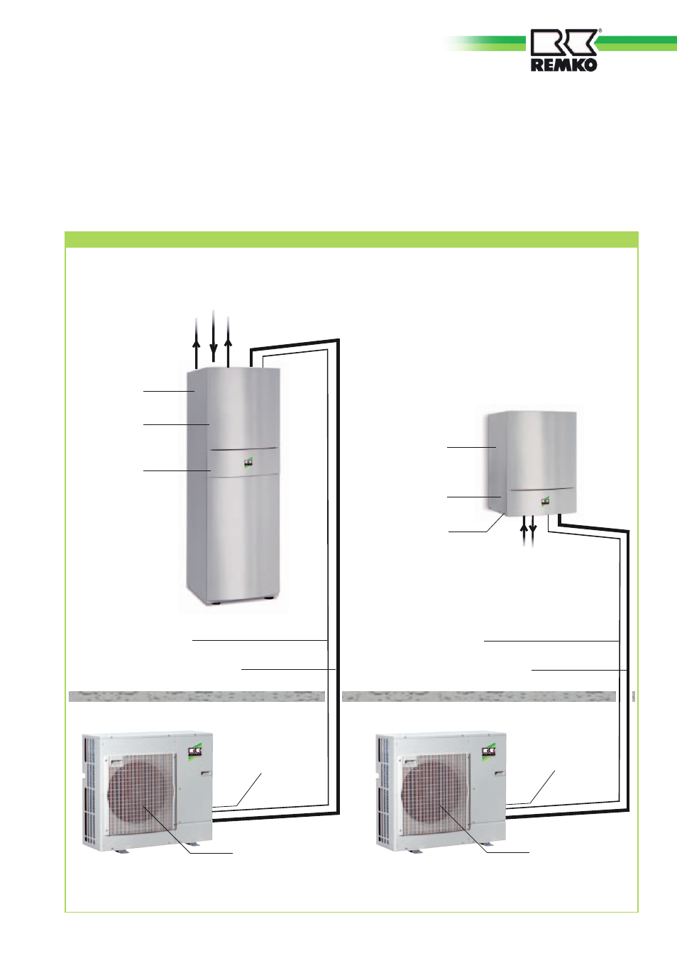
Outdoor unit CMT 120-1P
Indoor unit
CMT 120-1P
Fan
Outdoor area
Refrigerant lines
3
/
8
" and
5
/
8
"
Mains cable
Indoor unit
(3x1.5mm
2
)
Indoor area
condensate drain
(must be designed to be frost proof!)
* Mains supply
230V/1~50Hz 25A
(3x4 mm
2
)
Control cable (4x1 mm
2
)
Outdoor unit CMF 120-1P
Fan
condensate drain
(must be designed to be frost proof!)
Hot-water supply
and return pipes
(DN 25)
Mains cable
Electric booster
heater
3x(3x1.5 mm
2
)
Mains cable
Indoor unit
(3x1.5mm
2
)
Mains cable
Electric booster
heater (optional)
3x(3x1.5 mm
2
)
condensate drain
Refrigerant lines
3
/
8
" and
5
/
8
"
Control cable (4x1 mm
2
)
Inlet for
Heating (DN 25)
Common
Return pipe (DN 25)
Supply pipe for hot-
water tank (DN 25)
Indoor unit
CMF 120-1P
Installation instructions
The indoor and outdoor modules
have to be connected with
refrigerant lines of dimensions
3
/
8
"
(ca. 16 mm) and
5
/
8
" (ca. 10 mm).
A four-wire control cable has to be
laid between the two modules.
Both the indoor and outdoor
modules require a separate power
supply.
* Mains supply
230V/1~50Hz 25A
(3x4 mm
2
)
System Layout CMF 120-1P / CMT 120-1P
13