Remko wkf duo – REMKO WKF 120 Duo User Manual
Page 36
n
The heat pump requires a constant, minimum
medium volume of approx. 10 litres per kW of
heating capacity to guarantee power for
defrosting and to assure a minimum running
time.
n
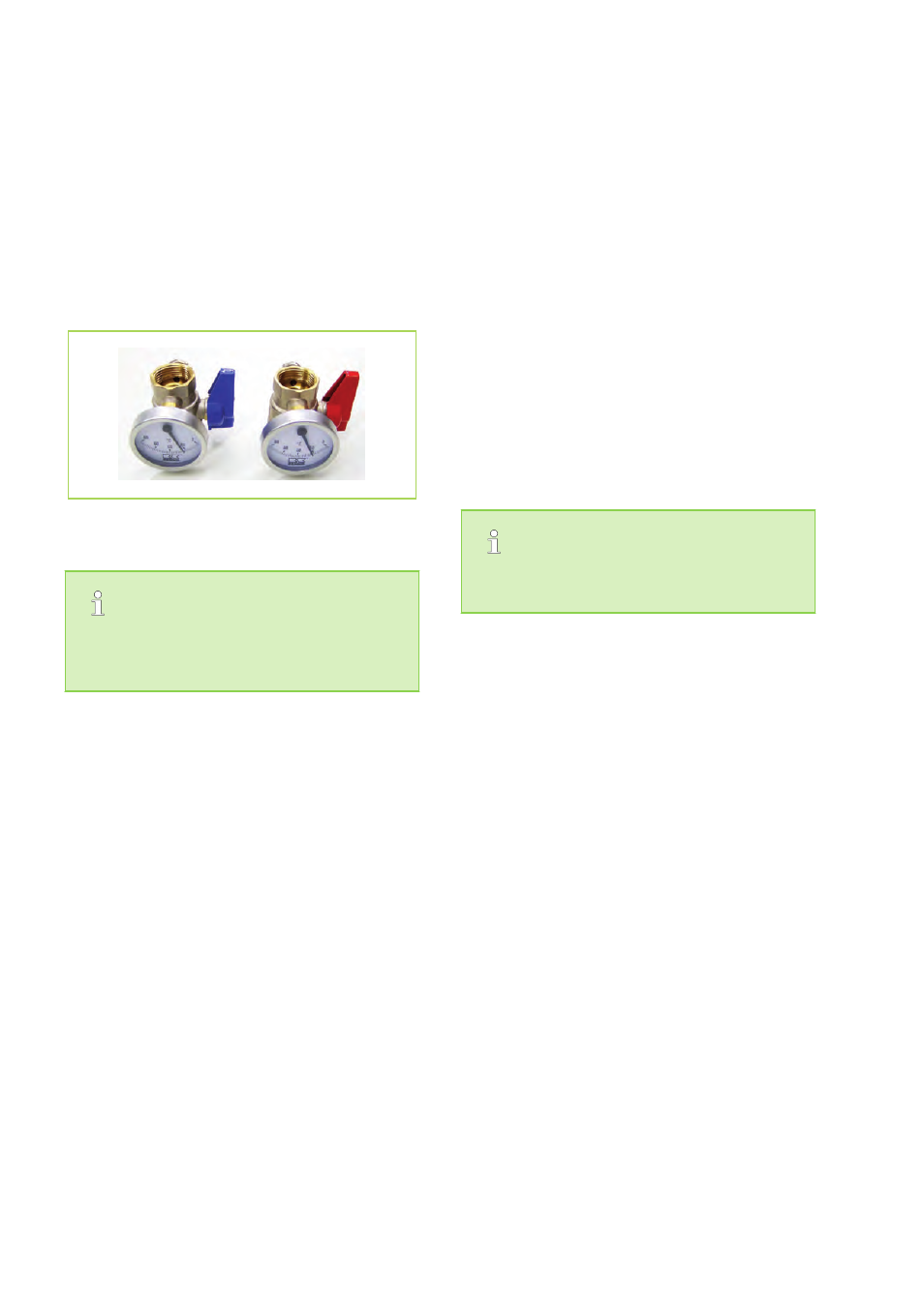
The stop cocks supplied are to be positioned
directly at the connections for the heat pump
inlet and return heating circuit. The shut-off
valves each contain a thermometer.
Fig. 38: Shut-off valves
Turning the thermometer heads serves to close
or open the stop valves! The dial be brought
into the desired position.
n
Install the dirt traps delivered with the unit out-
side the heat pump in the return flow. Ensure
that the dirt trap remains accessible for inspec-
tion.
n
Be sure to position one gate valve upstream
and another downstream of the dirt traps. This
ensures that the dirt traps can be checked at
any time without loosing water.
n
The dirt traps must be checked each time
maintenance is performed on the system.
n
Additionally, a hand-operated bleeder is
installed on the indoor unit for additional
bleeding of the heat pump.
n
All visible metallic surfaces must be addition-
ally insulated.
n
Cooling mode via the heating circuit requires a
completely vapour diffusion tight insulation
along the entire length of the pipework.
n
All outgoing heating circuits, including the con-
nections for water heating, are to be secured
against circulating water by means of check
valves.
n
Before being placed in service, the system
must be thoroughly flushed. Conduct a seal
test and perform a thorough bleeding of both
the indoor unit and the entire system according
to DIN standards - repeatedly, if necessary.
Actual schemas for hydraulic integration can
be found on the internet at www.remko.de
REMKO WKF Duo
36