5 hydraulic connection, Hydraulic connection – REMKO WKF 120 Duo User Manual
Page 35
Safe drainage in the event of leakages
The REMKO oil separator OA 2.2 fulfils the fol-
lowing list of requirements from regional regula-
tions and laws.
NOTICE!
Local regulations or environmental laws, for
example the German Water Resource Law
(WHG), can require suitable precautions to
protect against uncontrolled draining in case of
leakage to provide for safe disposal of
escaping refrigerator oil or hazardous media.
NOTICE!
With the connection of an external drain line to
the oil separator, it must be kept frost-free.
5
Hydraulic connection
A separate interpretation of nominal flow rate
must be made for every system (see technical
data).
n
A buffer tank can be used as a hydraulic com-
pensator for the hydraulic isolation of the
heating circuit.
n
Make a pipe-network calculation before instal-
ling the heat pump. After installing the heat
pump, it is necessary to perform a hydraulic
balancing of the heating circuit.
n
Protect floor heating systems against exces-
sively high inlet temperatures.
n
Do not reduce pipe diameters for the inlet and
return connections to the heat pump before
connecting a buffer tank.
n
Plan for air bleed valves and drain-off taps at
appropriate places.
n
Flush the system's entire pipe network before
connecting the heat pump.
n
One or, where necessary, several expansion
vessels must be dimensioned for the entire
hydraulic system.
n
The system pressure of the entire pipe network
is to be matched to the hydraulic system and
must be checked when the heat pump is
turned off. Also update the static-pressure form
supplied with the heat pump.
n
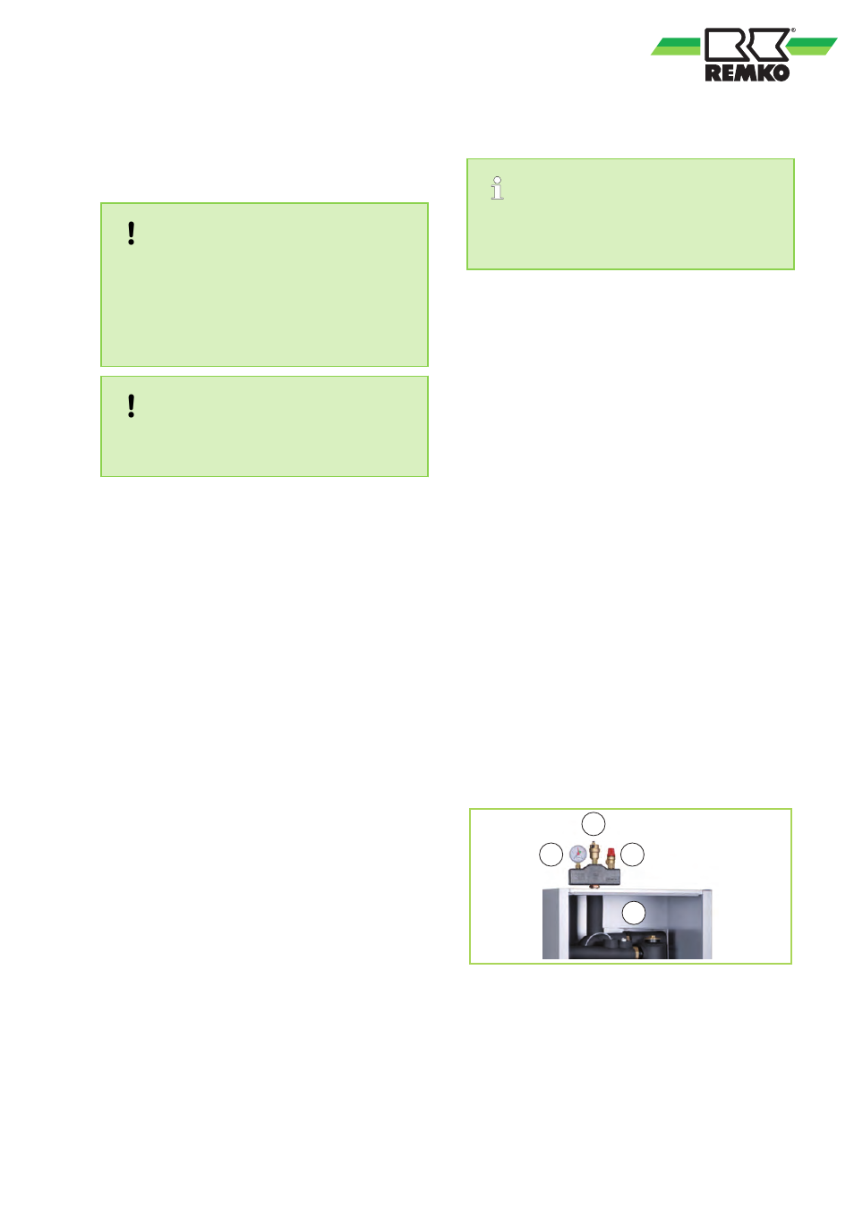
As delivered, the safety assembly consists of a
manometer, bleeder and safety valve. It is to
be mounted to the pipe connection provided on
the indoor unit.
2
1
3
4
Fig. 37: Safety assembly (similar to figure)
1: Manometer
2: Automatic bleeding valve
3: Safety valve
4: Indoor unit
35