Time, Temperature – REMKO WKF 120 Duo User Manual
Page 25
n
Ideal for bivalent mode to save energy.
n
High level of operational availability, thanks to
inverter technology.
Split AC unit
The REMKO inverter heat pump is a so-called split
unit. This means that it consists of an outdoor unit
and an indoor unit, both of which are connected via
refrigerant-carrying copper pipes. Thus there are
no water-carrying pipes laid from the indoors to
outdoors which need to be made frost proof. The
outdoor unit consists only of the condenser, the
evaporator and the expansion valve. This means
that the outdoor unit is considerably smaller. The
indoor unit contains the system's condenser and
the connections for the heating network.
REMKO inverter technology
The condenser of the heat pump is equipped with
a need-dependent speed control. The capacity
control for conventional heat pumps only recog-
nises the two statuses "ON" (full capacity) and
"OFF" (no capacity). The heat pump turns on
below a specified temperature and turns off when
this temperature is reached. This type of capacity
control is very inefficient. The capacity control on
the REMKO inverter heat pump is modulated to
suit actual demand. The electronics system has an
integrated frequency-converter which serves to
modify the condenser speed and the speed of the
fan as required. The condenser works at a higher
speed when under full load than under partial load.
The lower speeds ensure a longer operational life-
time for the components, improved coefficient of
performance and lower noise. Lower speeds also
result in lower energy consumption (electricity) and
longer service life. I.e.: inverter heat pumps will run
practically throughout the heating season. In all,
the highest efficiency possible.
1/3
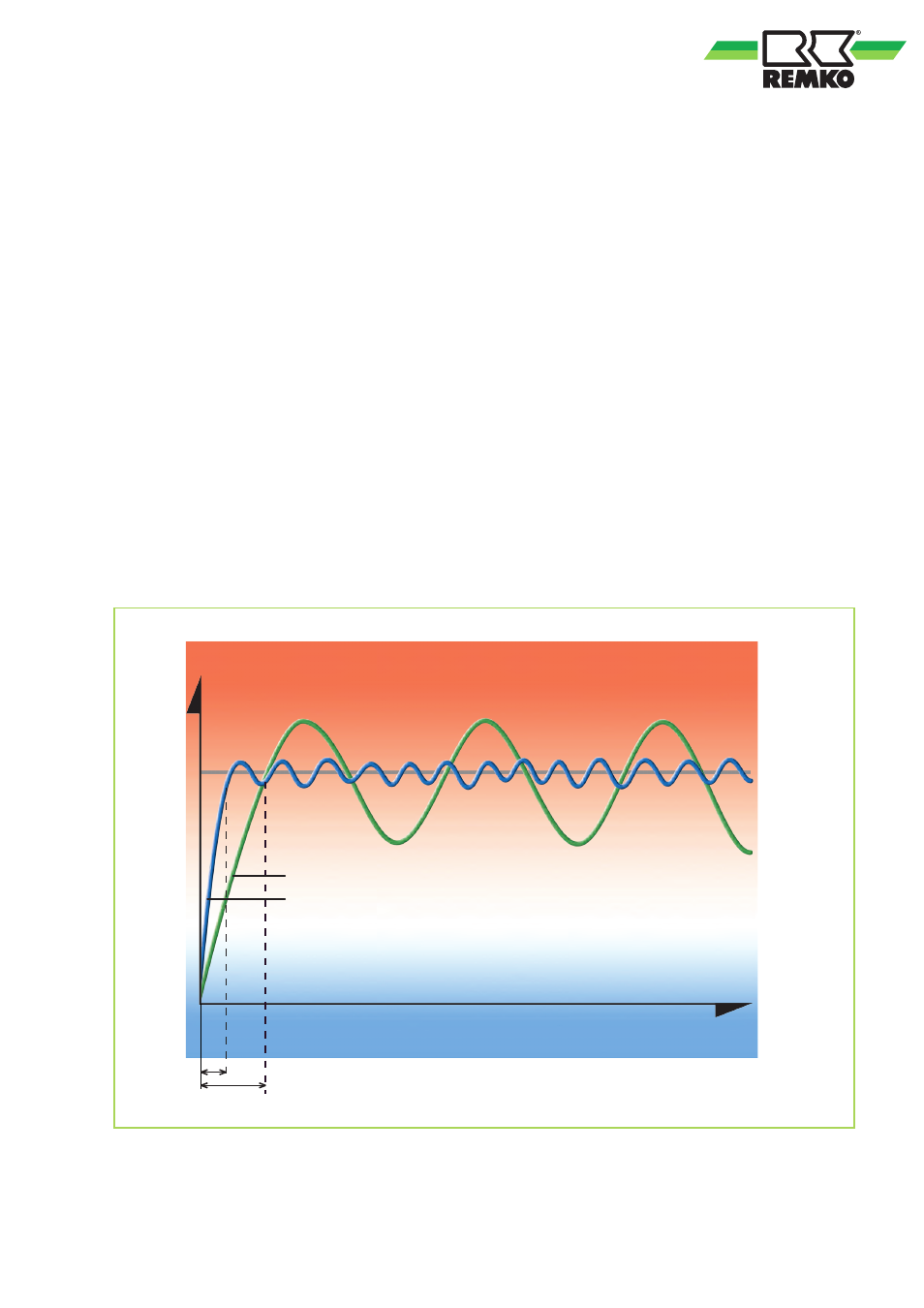
When it is switched on, the inverter only requires
one-third of the time of conventional systems
Time
Minimal temperature fluctuations
mean energy savings
Conventional
Inverter
Temperature
Fig. 24: Modern inverter technology
25