System state return -21, 9 basic setup and operation -21, Remote operation using commands -21 – Quantum Composers LDDC 1550 User Manual
Page 21: 9 basic setup and operation, System state return, Remote operation using commands
9-21 |
P a g e
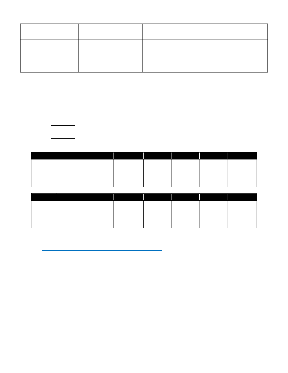
:QE
0 or 1
0 or 1
Q-switch trigger enable.
0 = disable, 1 = enable.
:SY
0 - Disabled
1 - Pulse Control
2 - Q-switch
3 - Pulse Control/Q-
Switch
0 - Disabled
1 - Pulse Control
2 - Q-switch
3 - Pulse Control/Q-
Switch
Sync output setting.
System State Return
The system state return is represented by a 16 bit binary number in which only the first 6 bits are
utilized. As seen below, each bit represents an individual state (Crowbar status, Interlock status,
etc.). Upon sending the System State query command, a decimal representation of the binary
status bits will be returned.
Example 1: Crowbar = Closed, Over Temp = OK, Interlock = Closed, Fault = No Fault,
Ready = 1, Active = Stop, Enable = Active 1010001 = 85
Example 2: Crowbar = Open, Over Temp = Fault, Interlock = Open, Fault = Fault,
Ready = 0, Active = Stop, Enable = Inactive 0101000 = 40
7
6
5
4
3
2
1
0
Unused
Crowbar
0 = Open
1 = Closed
Over
Temp
0 = OK
1 = Fault
Interlock
0 = Open
1 = Closed
Fault
0 = No
Fault
1 = Fault
Ready
0 = Not
Ready
1= Ready
Active
0 = Stop
1 = Start
Enable
0 = Inactive
1 = Active
15
14
13
12
11
10
9
8
Unused
Unused
Unused
Unused
Unused
Unused
Q-SW
Mode
0 = Disable
1 = Enabled
Ext Trig
0 = Disable
1 = Enabled
9 Basic Setup and Operation
The LDDC/LSC has multiple functions and parameters which provides the potential for a
number of modes of operation. The following sections will outline a sequential list to be carried
out regarding basic start-up and operation pertaining to different scenarios:
Remote Operation Using Commands
The first example will concentrate on remote communications-based (via USB) operation that
requires the Diode Driver to supply power at a constant level while utilizing the Interlock
Control and Pulse Mode features.
1.
First, ensure required USB drivers are already installed. Connect the LDDC/LSC to the
remote communications computer via USB.
2.
Connect the LDDC/LSC to the Diode Driver Supply with a DB16 connector. If the
Diode Driver has the option of providing an auxiliary +15VDC (200mA) through pins 13