8 command set -16, Device command format -16, 8 command set – Quantum Composers LDDC 1550 User Manual
Page 16
8-16 |
P a g e
6
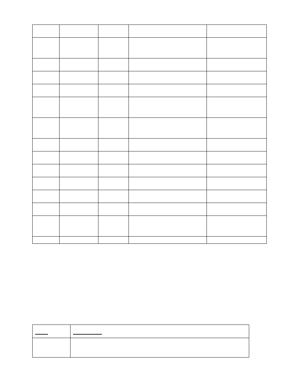
GND
Ground
Signal Ground
0V
7
External
Trigger
Input
External trigger input
2 to 20VDC
8
GND
Ground
Signal Ground
0V
9
ThermistorA+ Input
NTC/PTC thermistor input(+)
5K to 100K (typ)
10
ThermistorA- Input
NTC/PTC thermistor input(-)
5K to 100K (typ)
11
Photodiode
Anode
Input
Photodiode anode input
Photoconductive mode
12
Photodiode
Cathode
Input
Photodiode cathode input
Photoconductive mode
13
ThermistorB+ Input
NTC/PTC thermistor input(+)
5K to 100K (typ)
14
ThermistorB-
Input
NTC/PTC thermistor input(-)
5K to 100K (typ)
15
Analog Input
Input
Spare analog input
0-5VDC
16
Input #1
Input
Spare input #1
0-5VDC
17
Input #2
Input
Spare input #2
0-5VDC
18
Input #3
Input
Spare input #3
0-5VDC
19
Analog
Output
Output
Spare analog output
0-10VDC
20
GND
Ground
Signal Ground
0V
8 Command Set
The LDDC/LSC communicates via a standard USB type B connection. The unit operates in a
serial emulation mode in which the host computer will recognize the LDDC/LSC controller on a
serial port.
Device Command Format
All commands use ASCII characters and are composed of the following fields:
Field
Description
Prefix
Single semicolon character ";", must precede all commands. The device
will reset its command input buffer when the prefix is received.