Installation (cont.) – MovinCool CMW30 User Manual
Page 33
33
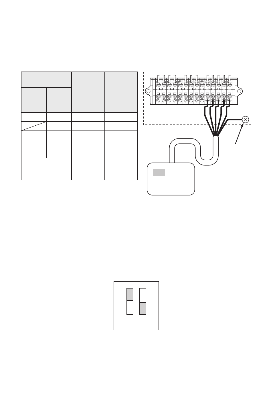
INSTALLATION (cont.)
Field-Supplied Millivolt Wall Thermostat Connection
(cont.)
Note:
1. Terminal No. G1 is used only with the wall thermostat that has Fan Hi-Lo speed
control.
2. Use the wall thermostat that is compatible with the millivolt system.
Do not connect the wall thermostat to AC or DC power source.
6. DIP switch #1 of DSW1 on the relay board must be in the ON position to use
the millivolt wall thermostat.
Note:
1. Default position of all DIP switches are the OFF position.
2. If #1 switch of DSW1 is in the OFF position, the wall mounted controller is
enabled.
L–
L+
E–
E+
G4
C4
P
RC
Y1
Y2
G
G1
G
UNIT TERMINAL
GROUND
SCREW
WALL THERMOSTAT
(Example of the multi stage system)
CONNECTION TABLE
Wall Thermostat
Terminal No.
Unit
Terminal
No.
Function
Single-
Stage
System
RC
Y
G
(G1)
R
Y1
Y2
G
(G1)
Common
Cool MIN
Cool MAX
Fan Hi
(Fan Lo)
RC
Y1
Y2
G
(G1)
(Shield Wire)
Ground
G
(Ground
Screw)
Multi-
Stage
System
ILL00304-00
ON
OFF
1
2
DSW1
ILL00305-00