Installation (cont.) – MovinCool CMW30 User Manual
Page 30
30
INSTALLATION (cont.)
Supplied Wall Mounted Controller Connection (cont.)
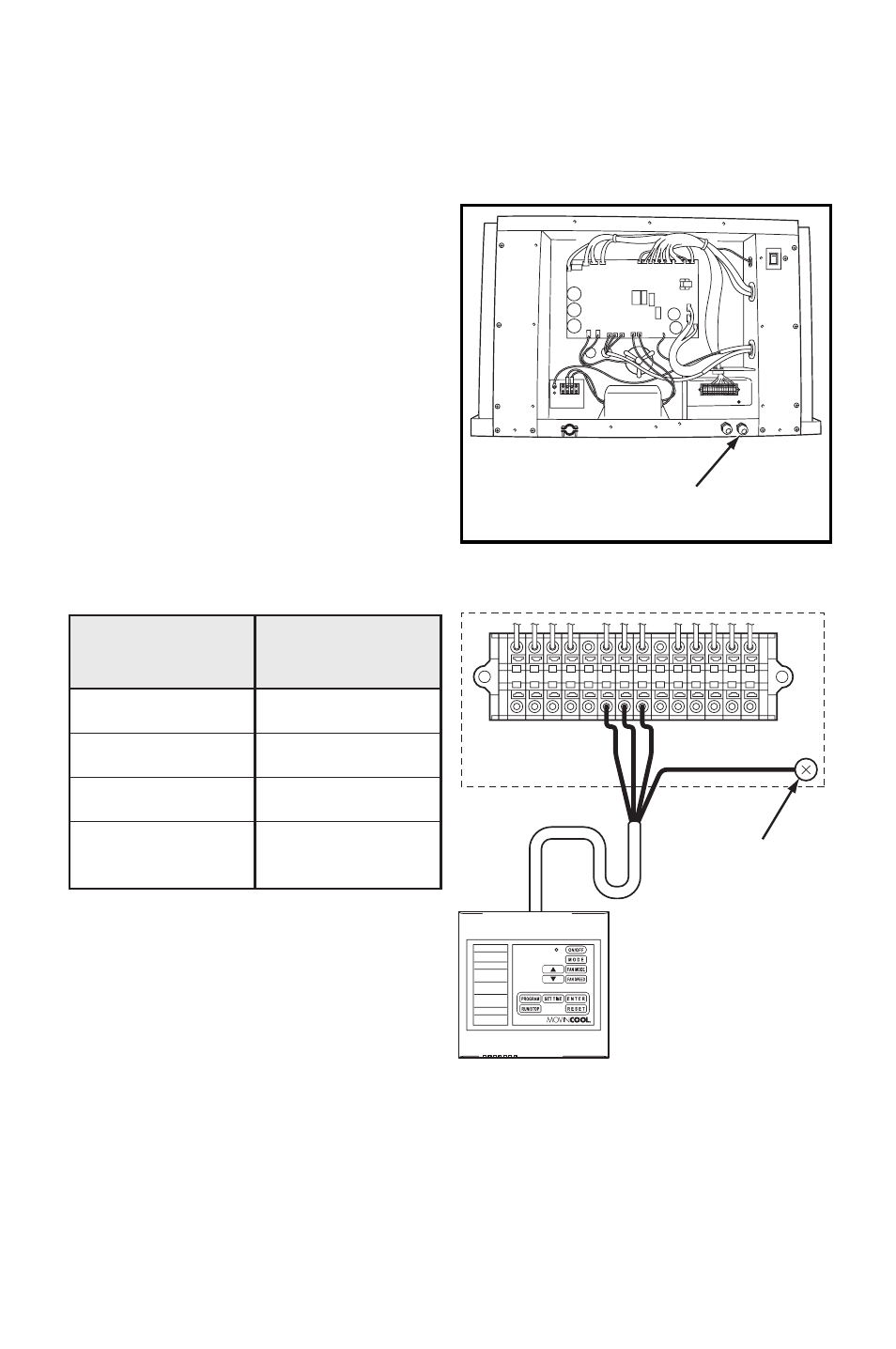
9. Disconnect power before connecting the wall mounted controller to the unit.
10. Insert the shield wire through the
wall mounted controller wire inlet.
Connect the shield wire to the
terminal block referring to the
connection table shown below.
Note: If wiring needs to be extended, a
maximum extension wire can be
extended up to 316 feet.
Shield wire 16-22 AWG is recommended
to use as an extension wire to reduce
noise interference.
Recommended extension wire: Shield
wire 16-22 AWG, Length 316 feet
maximum
Note: Do not connect the controller to AC or DC power source.
WALL MOUNTED
CONTROLLER WIRE INLET
ILL00300-00
L–
L+
E–
E+
G4
C4
P
RC
Y1
Y2
G
G1
G
UNIT TERMINAL
WALL MOUNTED
CONTROLLER
GROUND
SCREW
CONNECTION TABLE
P (Red)
C4 (White)
G4 (Black)
Shield Conductor
(Green)
P
Wall Mounted
Controller
Wire No. (Color)
Unit
Terminal No.
C4
G4
G
(Ground Screw)
ILL00301-00