Installation, Warning, Installing and framing the fireplace – Montigo B34DV User Manual
Page 4: Page 4 b-series dv-2 gas fireplace, Framing, Clearances, Top view front view side view
Page 4
B-Series DV-2 Gas Fireplace
Part No. XG0160 -141231
Installation
Installing and Framing the Fireplace
The
B-Series-DV-2
fireplaces may be installed in any location that main-
tains proper clearances to air conditioning ducts, electrical wiring and
plumbing. Safety, as well as efficiency of operation, must be considered
when selecting the fireplace location. Try to select a location that does
not interfere with room traffic, has adequate ventilation, and offers an
accessible pathway for Direct Vent installation. Refer to page 5 - Vent
Installation for more information.
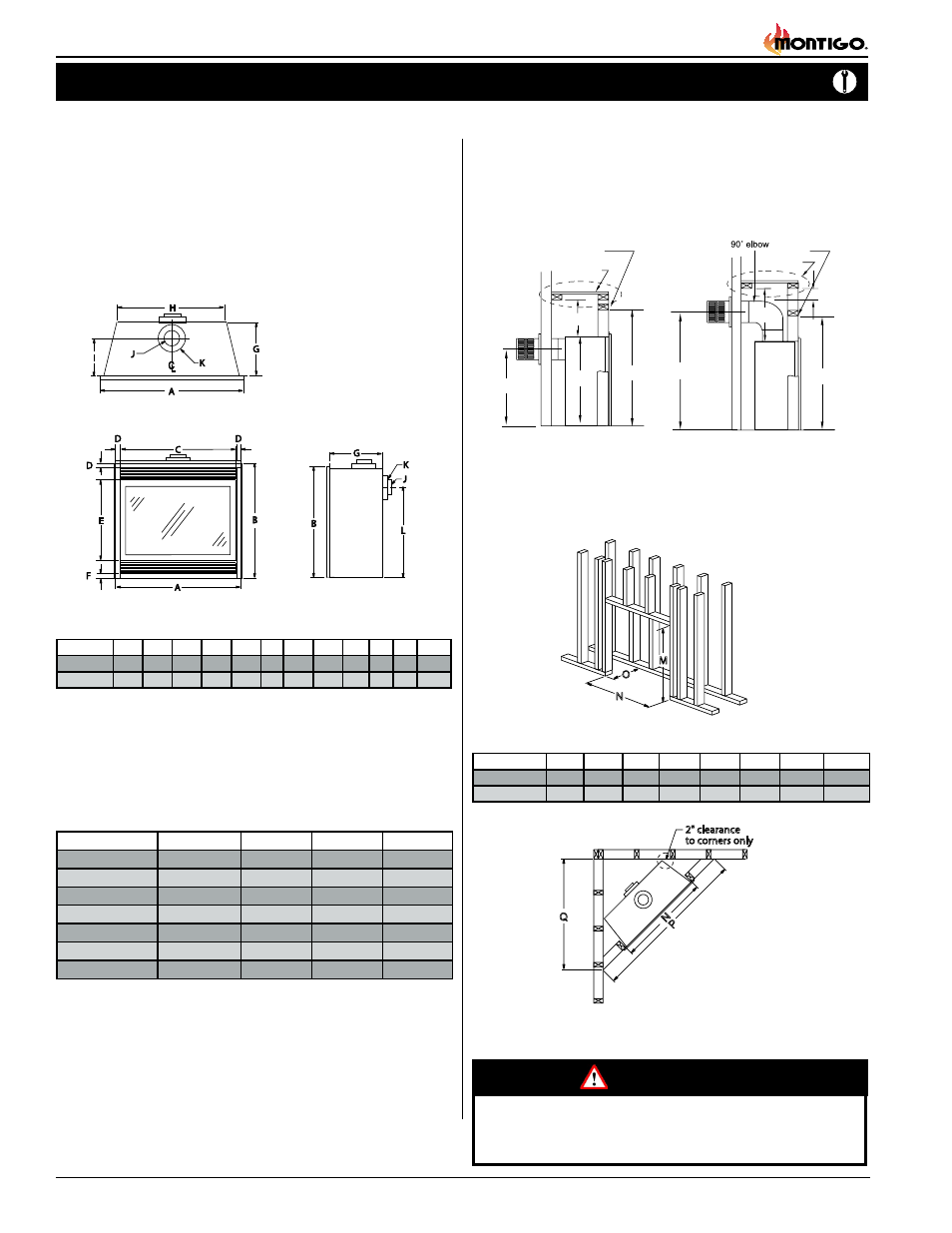
The fireplace dimensions are shown below:
Figure 4. Minimum Corner framing dimensions, using a 45° elbow.
Figure 3. Framing dimensions.
(
When sheetrock is
not used behind the
fireplace, framing
depth "O" may be
reduced by 5/8")
Framing
Top View
Front View
Side View
Clearances
These clearances apply to all dimensions except the framed opening,
where the clearance to combustibles is 0". The B-Series DV-2 clearances
to combustible materials are:
B34-DV-2-TV B34-DV-2 RV B38-DV-2-TV B38-DV-2-RV
Top - Rear Vent *
N/A
8"
N/A
9 1/4"
Top - Top Vent
15"
N/A
15"
N/A
Back
0"
1"
1"
1"
Sides
1"
1"
0"
0"
Floor
0"
0"
0"
0"
Mantle**
8"
8"
6"
6"
Flue
1 1/2"
1 1/2"
1"
1"
* Clearance from the top of the fireplace to a combustible ceiling
within the fireplace enclosure.
** Refer to page 12,
(Mantels and Surrounds).
Unprotected combustible walls which are perpendicular to the fireplace
opening, must not project beyond the area shown in Figure 23.
For protection against freezing temperatures, it is recommended that
outer walls of the chase be insulated with a vapor barrier. This will reduce
the possibility of a cold-air convection current on the fireplace.
Figure 1. Fireplace dimensions.
M
N
O
N P
Q
2" clearance
to corners only
M
N
O
N P
Q
2" clearance
to corners only
M
N
O
N P
Q
2" clearance
to corners only
A
B
C
D
E
F
G
H
I
J
K
L
B34-DV-2 33
3
/
4
31
1
/
2
31
1
/
4
1
1
/
4
18
1 13
3
/
4
21
3
/
4
8
4
7 25
1
/
4
B38-DV-2 37
3
/
4
34
1
/
2
34
3
/
4
1
1
/
4
21
1 15
7
/
8
24
1
/
8
9
4
7 28
3
/
8
M
N
O
N P
Q
2" clearance
to corners only
M
N
O
N P
Q
2" clearance
to corners only
L
M
N
O
P
Q
S
T
B34-DV-2
25
1
/
4
36
3
/
4
33
15
1
/
2
50
35
3
/
8
30
3
/
8
39
7
/
8
B38-DV-2
28
3
/
8
39
3
/
4
37
17
5
/
8
56
39
5
/
8
33
3
/
8
42
7
/
8
When installing a shelf over the top of the fireplace, the following guidelines
must be adhered to: For Rear Vent applications the minimum clearance
from the top of the fireplace to a shelf is 8". For Top Vent applications, the
minimum clearance is 15". (
Minimum clearance to combustible construction
around the vent pipe is 1" on all sides, except on horizontal venting where the
top of the pipe must have a clearance of at least 2".
)
Figure 2. Framing for shelves over the fireplace.
Top Vent
Rear Vent
(On Applicable Models)
WARNING!
When this appliance is installed directly on any combustible mate-
rial other than wood flooring, it must be installed on a metal or
wood panel extending the full width and depth of the appliance.
M
8”
S
Header
Shelf
L
T
15”
Header
MEL Short
Shelf
M
2” Min