8 cable & screw terminal board – Measurement Computing PCM-DAS16D/12 User Manual
Page 29
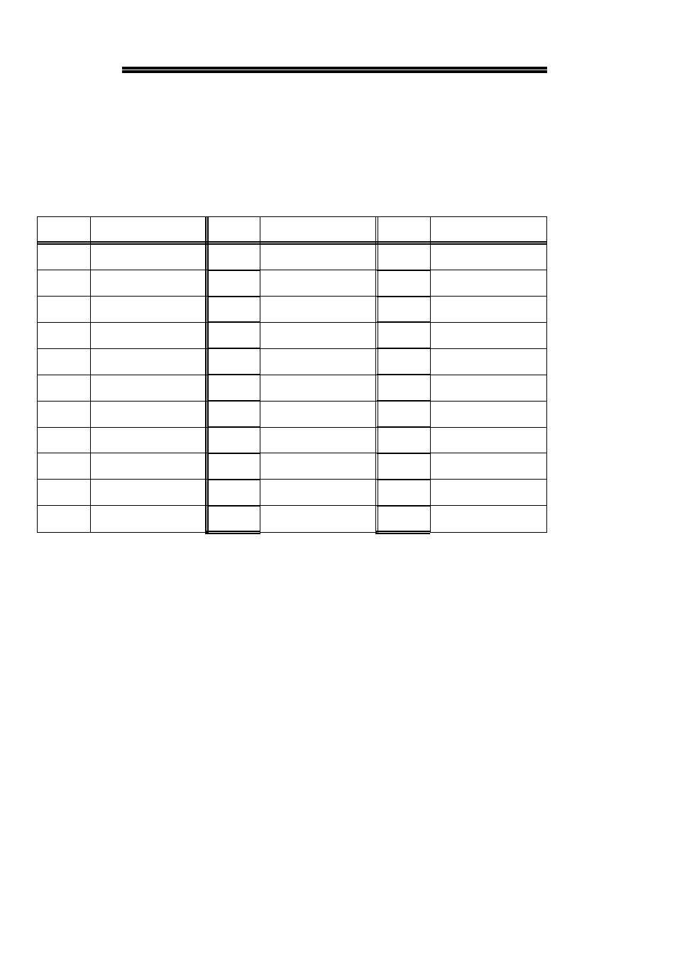
8 CABLE & SCREW TERMINAL BOARD
The PCM-C37/33 is a 10 inch 33 conductor cable assembly for use with 33
pin PCMCIA cards. The PCM-C37/33 has a connector on one end and a 37
pin D type connector at the other. The chart below describes the color coding
of the wires for each of the 33 pins.
Blue/Red
33
Blue
22
White/Red
11
Grey/White
32
Green
21
White/Green
10
Black/White
31
White
20
White/Orange
9
Red/White
30
Green/Yellow
19
White/Brown
8
Green/White
29
Green/Red
18
White/Blue
7
Orange/White
28
Red/Green
17
Tan
6
Brown/White
27
Orange/Red
16
Violet
5
Blue/White
26
Red/Orange
15
Orange
4
Pink
25
Red/Blue
14
Brown
3
Grey
24
White/Grey
13
Red
2
Yellow
23
White/Black
12
Black
1
COLOR
PIN
COLOR
PIN
COLOR
PIN
If you want to wire directly to your signal source, simply cut off the 37 pin
connector and wire up the signals using the color to pin number guide above.
If you wish to use a screw terminal board, please purchase a CIO-MINI37 and
connect it to the 37 pin connector end of the cable. Of course pins 34 to 37
will not have any function. Use the PCM-DAS16x/12 connector diagram
elsewhere in this manual to determine the function of the signals at the screw
terminals. The screw terminals are numbered 1 to 37, and the cable is wired
so pin 1 of the PCM board connects to pin 1 of the screw terminal, and so on.
25