3 system grounds and isolation – Measurement Computing PCM-DAS16D/12 User Manual
Page 14
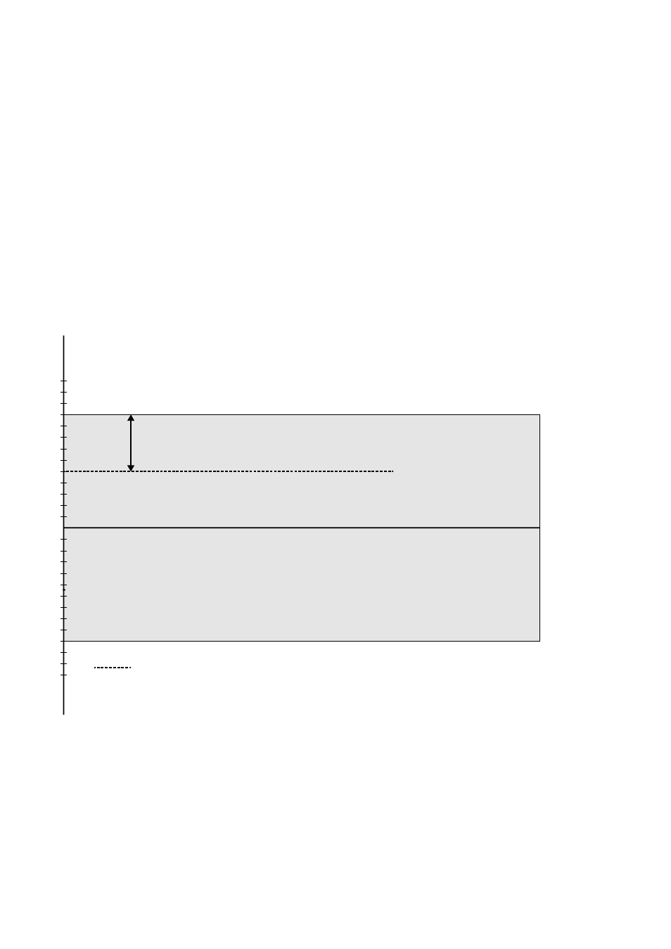
Before moving on to the discussion of grounding and isolation, it is important
to explain the concepts of common mode, and common mode range (CM
Range). Common mode voltage is depicted in the diagram below as Vcm.
Though differential inputs measure the voltage between two signals, without
(almost) respect to the either signal’s voltages relative to ground, there is a
limit to how far away from ground either signal can go. Though the PCM-
DAS16x/12 has differential inputs, it will not measure the difference between
100V and 101V as 1 Volt (in fact the 100V would destroy the board!). This
limitation or common mode range is depicted graphically in the following
diagram. The PCM-DAS16x/12 common mode range is +/- 10 Volts. Even in
differential mode, no input signal can be measured if it is more than 10V
from the board’s low level ground (LLGND).
4.1.3 System Grounds and Isolation
There are three scenarios possible when connecting your signal source to
your PCM-DAS16x/12 board.
10
+1V
-13V
+2V
-12V
+3V
-11V
+4V
-10V
+5V
-9V
+6V
-8V
+7V
-7V
+8V
-6V
+9V
-5V
+10V
-4V
+11V
-3V
+12V
-2V
+13V
-1V
Gray area represents common mode range
Both V+ and V- must always remain within
the common mode range relative to LL Gnd
Vcm (Common Mode Voltage) = +5 Volts
Vcm
With Vcm= +5VDC,
+Vs must be less than +5V, or the common mode range will be exceeded (>+10V)