2 common ground / differential inputs, 3 common mode voltage < ±10v / single ended inputs, A/d board – Measurement Computing PCM-DAS16D/12 User Manual
Page 20
However the reverse is not true. The diagram below shows a recommended connec-
tion diagram for a common ground / single-ended input system.
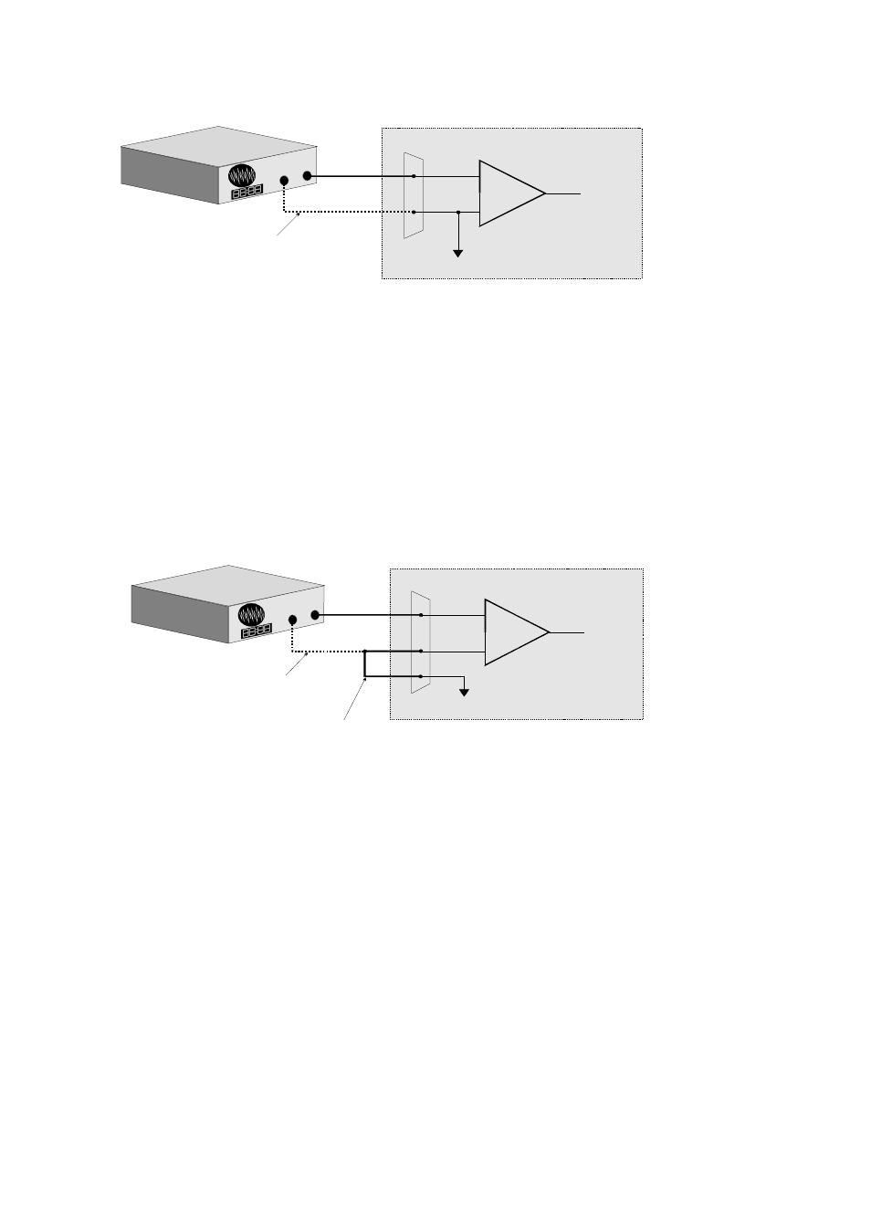
4.2.2 Common Ground / Differential Inputs
The use of differential inputs to monitor a signal source with a common ground is a
acceptable configuration though it requires more wiring and offers fewer channels
than selecting a single-ended configuration. The diagram below shows the recom-
mended connections in this configuration.
4.2.3 Common Mode Voltage < ±10V / Single Ended Inputs
This is not a recommended configuration. In fact, the phrase common mode has no
meaning in a single-ended system and this case would be better described as a system
with offset grounds. Anyway, you are welcome to try this configuration, no system
16
+
-
Input
Amp
To A/D
A/D Board
I/O
Connector
LL GND
CH IN
+
-
Sign
al
S
ourc
e wit
h
C
omm
on G
nd
Optional wire
since signal source
and A/D board share
common ground
Signal source and A/D board
sharing common ground connected
to single-ended input.
+
-
Input
Amp
To A/D
A/D Board
I/O
Connector
LL GND
CH High
CH Low
+
-
Sig
nal
S
ource
with
C
omm
on G
nd
Optional wire
since signal source
and A/D board share
common ground
Required connection
of LL GND to CH Low
Signal source and A/D board
sharing common ground connected
to differential input.