4 common mode voltage < ±10v /differential inputs, 5 common mode voltage > +/-10v, A/d board – Measurement Computing PCM-DAS16D/12 User Manual
Page 21
damage should occur and depending on the overall accuracy you require, you may
receive acceptable results.
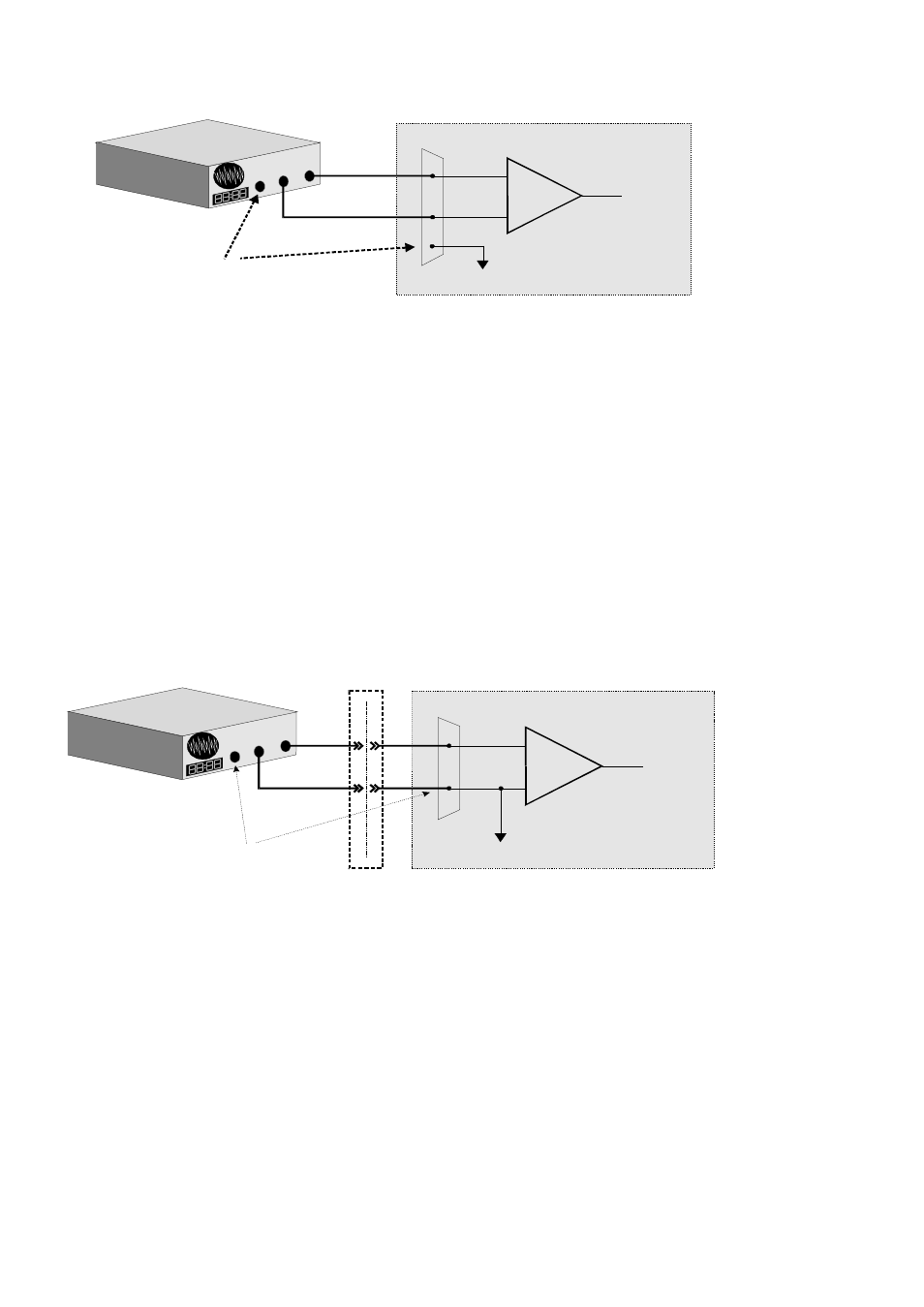
4.2.4 Common Mode Voltage < ±10V /Differential Inputs
Systems with varying ground potentials should always be monitored in the differential
mode. Care is required to assure that the sum of the input signal and the ground differ-
ential (referred to as the common mode voltage) does not exceed the common mode
range of the A/D board (+/-10V on the PCM-DAS16x/12). The diagram below show
recommended connections in this configuration.
4.2.5 Common Mode Voltage > +/-10V
The PCM-DAS16x/12 will not directly monitor signals with common mode voltages
greater than +/-10V. You will either need to alter the system ground configuration to
17
+
-
Input
Amp
To A/D
A/D Board
I/O
Connector
LL GND
CH High
CH Low
+
-
Sign
al So
urce
w
ith C
omm
on
Mo
de V
oltag
e
Signal source and A/D board
with common mode voltage
connected to a differential input.
GND
The voltage differential
between these grounds,
added to the maximum
input signal must stay
within +/-10V
System with a Large Common Mode Voltage,
Connected to a Single-Ended Input
I/O
Connector
+
-
Input
Amp
To A/D
LL GND
CH IN
A/D Board
+
-
L
arge
comm
on
m
ode v
oltag
e
be
twee
n sig
nal
sou
rce &
A/D
boar
d
GND
Isolation
Barrier
When the voltage difference
between signal source and
A/D board ground is large
enough so the A/D board’s
common mode range is
exceeded, isolated signal
conditioning must be added.