Digital input terminals (ip0a to ip15b), Extending the input range, Digital input terminals (ip0a to ip15b) -5 – Measurement Computing E-PDISO16 User Manual
Page 18
E-PDISO16 User's Guide
Functional Details
Digital input terminals (IP0A to IP15B)
The E-PDISO16 has 16 isolated digital inputs. Connect up to 16 isolated differential digital input signals using
the following screw terminal pairs:
!
IP0A and IP0B
!
IP8A and IP8B
!
IP1A and IP1B
!
IP9A and IP9B
!
IP2A and IP2B
!
IP10A and IP10B
!
IP3A and IP3B
!
IP11A and IP11B
!
IP4A and IP4B
!
IP12A and IP12B
!
IP5A and IP5B
!
IP13A and IP13B
!
IP6A and IP6B
!
IP14A and IP14B
!
IP7A and IP7B
!
IP15A and IP15B
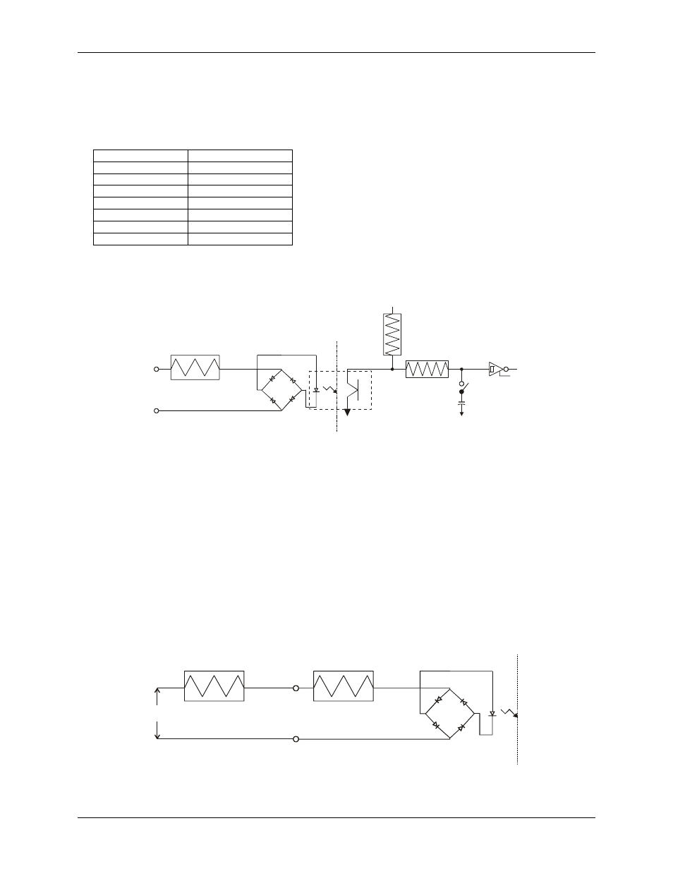
A schematic of a single channel is shown in
. The signals are routed through a bridge rectifier so that
the inputs are not polarity-sensitive. It can be driven by either AC (50 - 1000 Hz) or DC voltage up to ±30
VDC.
Figure 3-4. Single-channel configuration
1.6 K
Isolated Input
Not Polarized
Circuitry Sharing
PC Ground
Filter Switch
0.1uF
47K
+5V
100K
The 16 optically-isolated (500 V) inputs can be read back as a single byte. Each input has a software-controlled
filter with a time constant of 5 ms (200 Hz). The filter is required for AC inputs, and recommended for almost
all DC inputs. Unless you have a good reason to turn off a filter, we recommend that you enable it.
Extending the input range
To extend the input range beyond the 5 to 30 V specified, add an external resistor.
shows the external
resistor (R
ext
) and the equations used to calculate resistor values for a given V
in
. The equation R
ext
= 100 * (V
in
–
30) calculates the resistor value for a given V
in
.
Figure 3-5. External resistor added to extend input range
Make sure the external resistor is capable of handling the power generated by the input. Calculate the power
requirement in watts (P
w
) using the equation P
w
= R
ext
/10000.
1.6 K
Isolated Input
Not Polarized
R ext
R ext = 100 * (Vin - 30)
Pw = R ext / 10,000
V in
3-5