Factory default button, Screw terminal wiring, Factory default button -3 – Measurement Computing E-PDISO16 User Manual
Page 16: Screw terminal wiring -3
E-PDISO16 User's Guide
Functional Details
Factory default button
The factory default button resets the Ethernet parameters, filter, and relay conditions on the E-PDISO16 to the
factory default settings. Press and hold this button for three seconds to reset the E-PDISO16 to the factory
default configuration.
Screw terminal wiring
The E-PDISO16 has three rows of screw terminals for digital input and relay output connections. Use 14 AWG
to 20 AWG wire for your signal connections.
Caution! Keep the length of stripped wire at a minimum to avoid a short to the enclosure. When
connecting your field wiring to the screw terminals, use the strip gage on the terminal strip, or
strip to 5.5 - 7.0 mm (0.215" to 0.275") long.
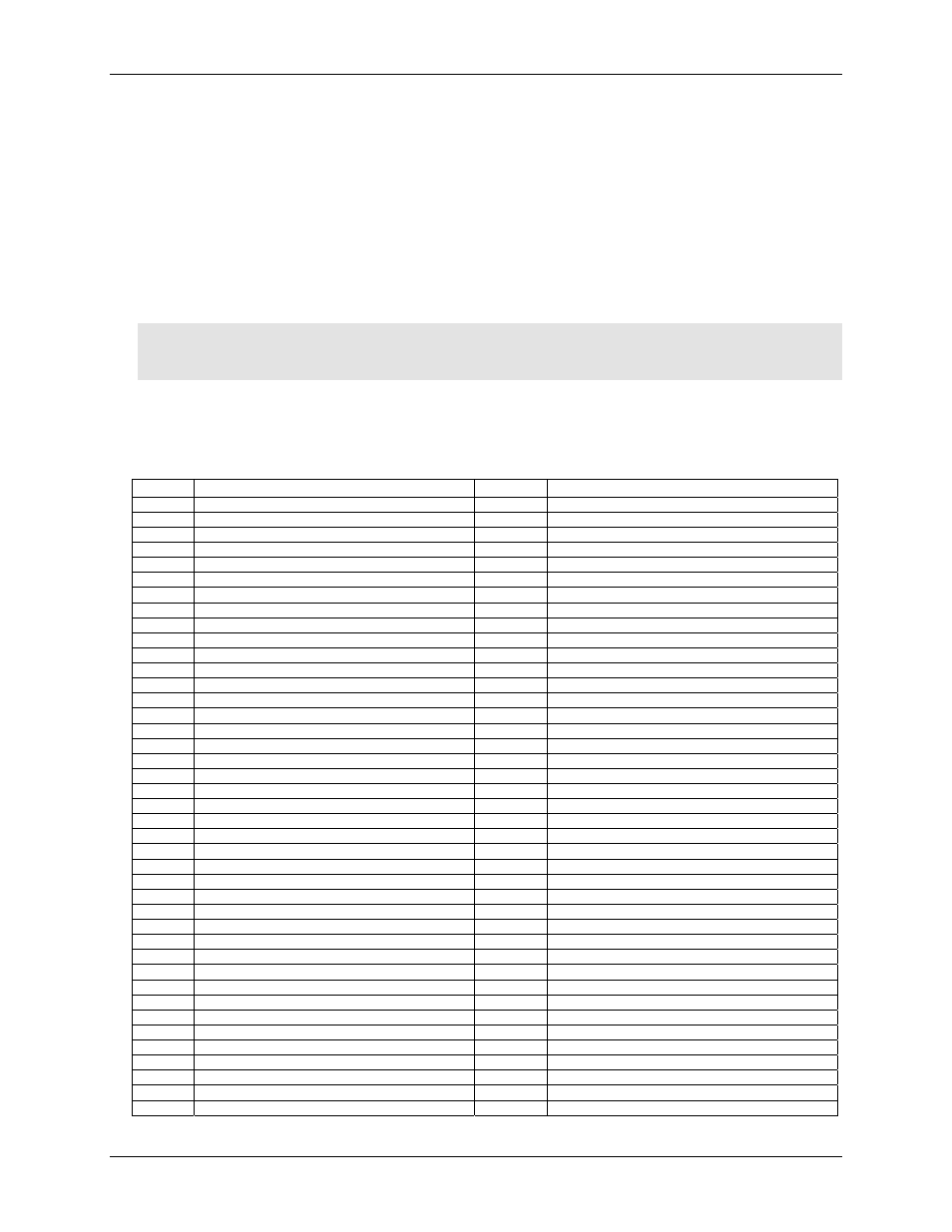
Each screw terminal is identified with a label on the module and on the underside of the enclosure lid. Refer to
Table 3-4 for the signal name associated with each module label.
Table 3-4. Module labels and associated signal names
Pin
Signal Name
Pin
Signal Name
IP0A
Input 0 terminal A
IP8A
Input 8 terminal A
IP0B
Input 0 terminal B
IP8B
Input 8 terminal B
IP1A
Input 1 terminal A
IP9A
Input 9 terminal A
IP1B
Input 1 terminal B
IP9B
Input 9 terminal B
IP2A
Input 2 terminal A
IP10A
Input 10 terminal A
IP2B
Input 2 terminal B
IP10B
Input10 terminal B
IP3A
Input 3 terminal A
IP11A
Input 11 terminal A
IP3B
Input 3 terminal B
IP11B
Input 11 terminal B
IP4A
Input 4 terminal A
IP12A
Input 12 terminal A
IP4B
Input 4 terminal B
IP12B
Input 12 terminal B
IP5A
Input 5 terminal A
IP13A
Input 13 terminal A
IP5B
Input 5 terminal B
IP13B
Input 13 terminal B
IP6A
Input 6 terminal A
IP14A
Input 14 terminal A
IP6B
Input 6 terminal B
IP14B
Input 14 terminal B
IP7A
Input 7 terminal A
IP15A
Input 15 terminal A
IP7B
Input 7 terminal B
IP15B
Input 15 terminal B
NO0
Relay 0 Normally Open contact
NO8
Relay 8 Normally Open contact
C0
Relay 0 Common contact
C8
Relay 8 Common contact
NC0
Relay 0 Normally Closed contact
NC8
Relay 8 Normally Closed contact
NO1
Relay 1 Normally Open contact
NO9
Relay 9 Normally Open contact
C1
Relay 1 Common contact
C9
Relay 9 Common contact
NC1
Relay 1 Normally Closed contact
NC9
Relay 9 Normally Closed contact
NO2
Relay 2 Normally Open contact
NO10
Relay 10 Normally Open contact
C2
Relay 2 Common contact
C10
Relay 10 Common contact
NC2
Relay 2 Normally Closed contact
NC10
Relay 10 Normally Closed contact
NO3
Relay 3 Normally Open contact
NO11
Relay 11 Normally Open contact
C3
Relay 3 Common contact
C11
Relay 11 Common contact
NC3
Relay 3 Normally Closed contact
NC11
Relay 11 Normally Closed contact
NO4
Relay 4 Normally Open contact
NO12
Relay 12 Normally Open contact
C4
Relay 4 Common contact
C12
Relay 12 Common contact
NC4
Relay 4 Normally Closed contact
NC12
Relay 12 Normally Closed contact
NO5
Relay 5 Normally Open contact
NO13
Relay 13 Normally Open contact
C5
Relay 5 Common contact
C13
Relay 13 Common contact
NC5
Relay 5 Normally Closed contact
NC13
Relay 13 Normally Closed contact
NO6
Relay 6 Normally Open contact
NO14
Relay 14 Normally Open contact
C6
Relay 6 Common contact
C14
Relay 14 Common contact
NC6
Relay 6 Normally Closed contact
NC14
Relay 14 Normally Closed contact
NO7
Relay 7 Normally Open contact
NO15
Relay 15 Normally Open contact
C7
Relay 7 Common contact
C15
Relay 15 Common contact
NC7
Relay 7 Normally Closed contact
NC15
Relay 15 Normally Closed contact
3-3