Relay output terminals (no0 to nc15), Form c relay output, Relay output terminals (no0 to nc15) -4 – Measurement Computing E-PDISO16 User Manual
Page 17
E-PDISO16 User's Guide
Functional Details
Relay output terminals (NO0 to NC15)
The E-PDISO16 provides 16 Form C electromechanical relay outputs. The Form C relay has a common (C),
normally open (NO) and normally closed (NC) contact.
The screw terminals labeled
NO0
to
NC7
connect to the NO, C, and NC contacts for relays 0 through 7. The
screw terminals labeled
NO8
to
NC15
connect to the NO, C, and NC contacts for relays 8 through 15.
Form C relay output
A schematic for Form C relay contacts is shown in
Figure 3-2. Form C relay contacts
Two 4.7 k pull-down resistor networks on the E-PDISO16 control the power-up state of each relay bank. At
power-up, the relays are put into a non-energized state (NC in contact to Common).
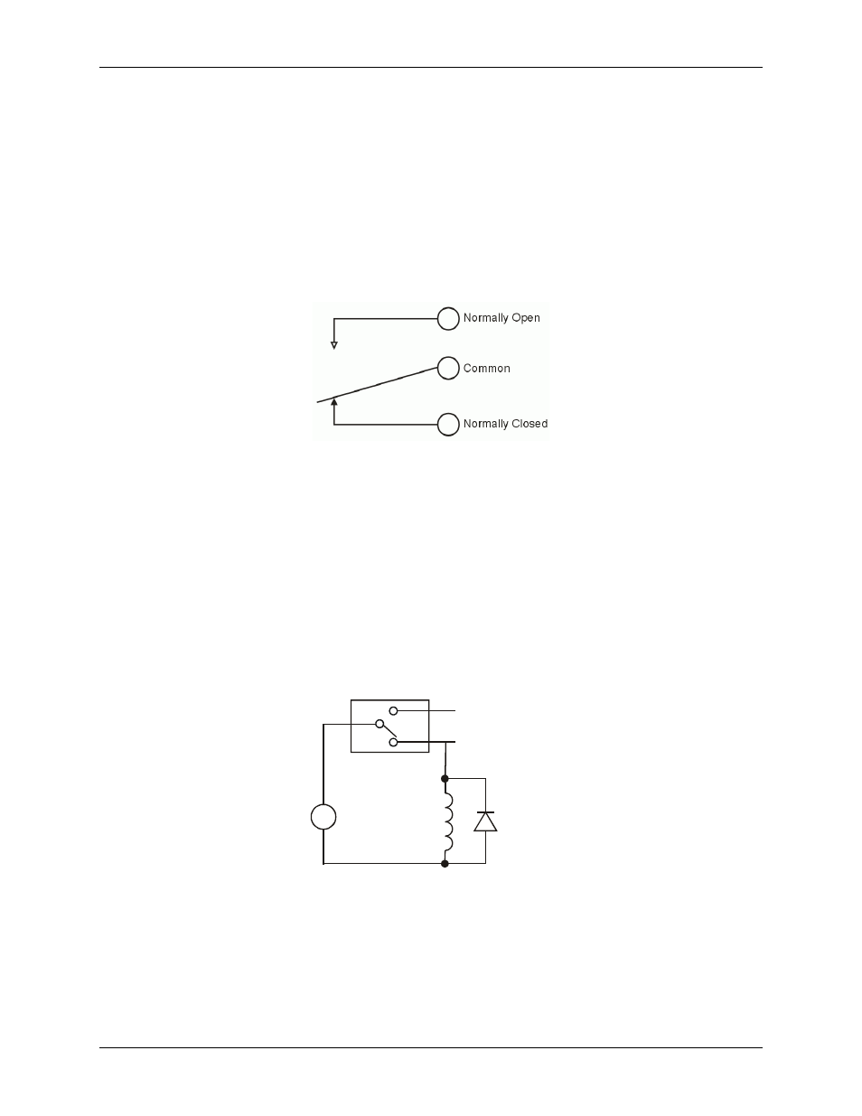
Relay contact protection circuit for inductive loads
If you are using the relays to control inductive loads, place a diode across the load terminals to suppress the
kickback voltage. If the diode is not present, the kickback voltage could cause the on-board processor to enter
an unstable state. To return the processor to a stable state, unplug the power cable from the E-PDISO16 and
then reconnect.
A contact protection circuit is shown in
. For AC loads, install a metal oxide varistor (MOV).
Figure 3-3. Relay contact protection circuit
C
V
Inductive
Load
Kickback
Diode
NC
+
-
NO
Relay
3-4