Functional details, Internal components, Ethernet port – Measurement Computing E-PDISO16 User Manual
Page 14: External power connectors, Functional details -1, Internal components -1, Ethernet port -1, External power connectors -1, Figure 3-1, Chapter 3
Chapter 3
Functional Details
Internal components
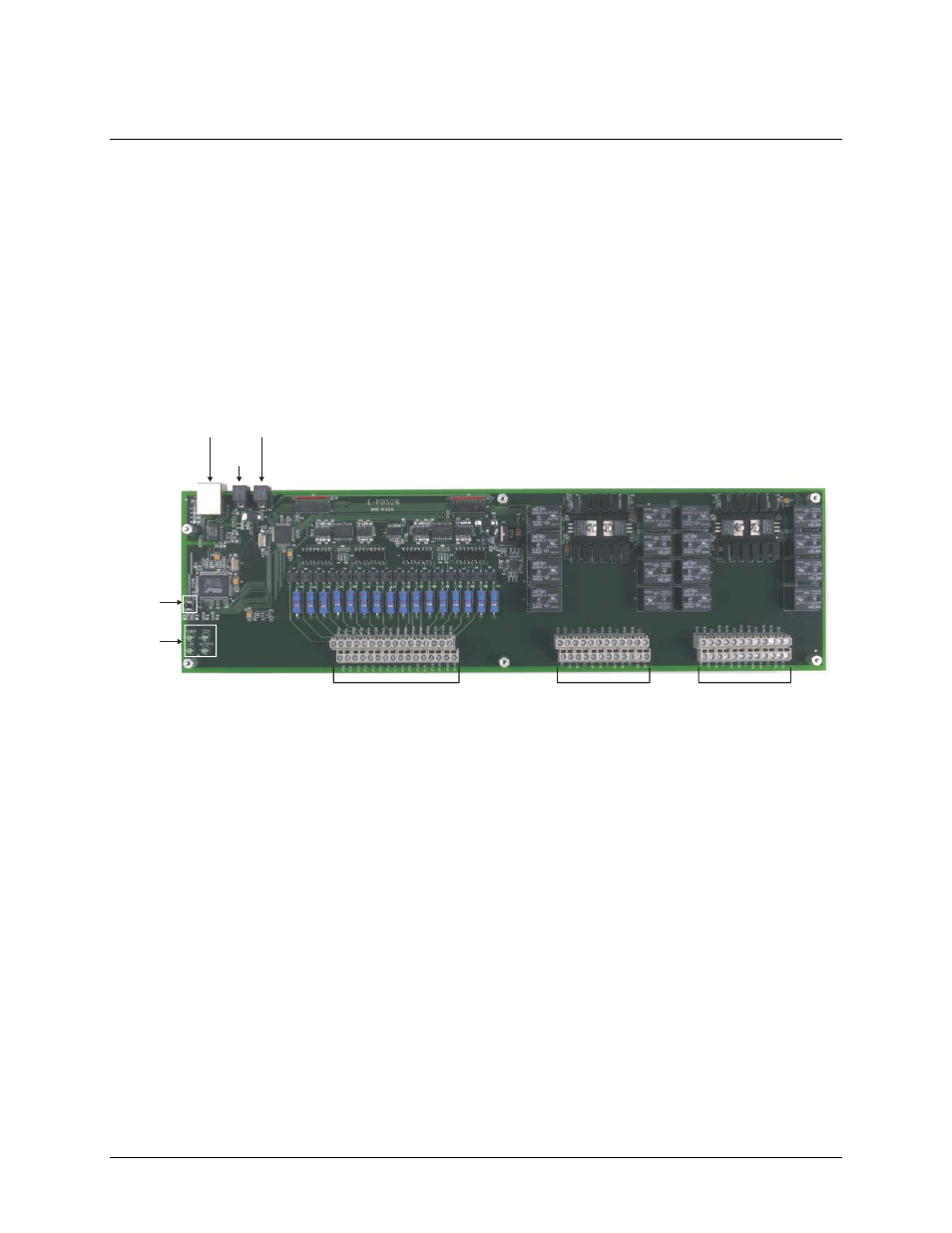
The E-PDISO16 has the following external components, as shown in Figure 3-1.
!
Ethernet port
!
Two (2) external power connectors
!
Four status LEDs (POWER, LINK, ACTIVITY, and TEST)
!
Factory default button
!
Screw terminal bank for 16 digital input connections (IP0A through IP15B)
!
Screw terminal bank for eight relay output connections (NO0 through NC7)
!
Screw terminal bank for eight relay output connections (NO8 through NC15)
Factory
Default
button
Power
OUT
Power
IN
Status
LEDs
Ethernet
Port
Screw terminals for
digital inputs IP0A to IP15B
Screw terminals for
relays N07 - NC7
Screw terminals for
relays N08 - Nc15
Figure 3-1. E-PDISO16 module components
Ethernet port
The E-PDISO16 has one 10/100 BASE-T, auto-negotiation, high-speed communication port. The port
connector is an RJ-45, eight-position connector. The Ethernet port accepts CAT-5 shielded or unshielded
twisted pair cable. The maximum communication distance without using a repeater is 100 meters. You can send
your data 100 meters at data speeds of up to 100 Mbps using only one Ethernet cable connected to your
computer.
External power connectors
The E-PDISO16 has two external power connectors labeled
Power IN
and
Power OUT
. Connect the
Power IN
connector to the supplied +9 V, external power supply (CB-PWR-9V3A). The
Power OUT
connector lets you
power additional Measurement Computing products from a single external power supply.
The maximum output current is 3 A. When running at full load, that is, when all relays are on and the Ethernet
is transferring data, the E-PDISO16 draws 1.7 A from the supply. Depending on your load requirements,
additional products may require a separate power supply.
3-1