Measurement Computing Personal488 rev.1.0 User Manual
Page 39
Personal488 for Windows 95/98/Me/NT/2000/XP
889496
Hardware Configuration Reference 4-13
The GP488B/MM interface board may be set to interrupt the PC on the occurrence of certain
hardware conditions. The level of the interrupt generated is set by JP3. The GP488B/MM
adheres to the “AT-style” interrupt sharing conventions. When an interrupt occurs, the
interrupting device must be reset by writing to I/O address 02FX, where X is the interrupt
level (from 0 to 7). This interrupt response level is set by switches 1, 2, and 3 of SW1 which
must be set to correspond to the JP3 interrupt level setting.
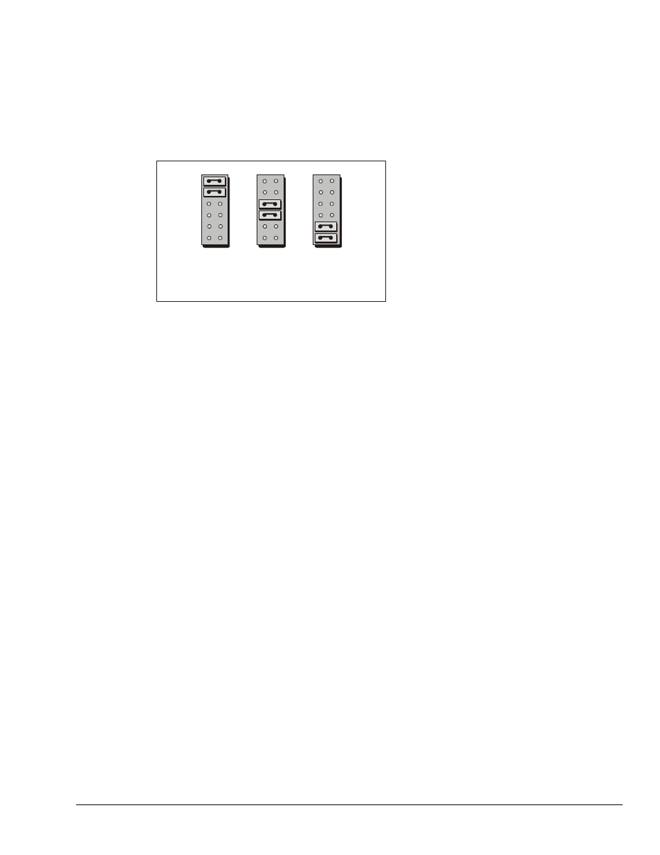
Configuring the GP488B/MM PC104 Interface DMA Channel
JP2
Channel 1
GP488B/MM PC104 DMA Channel Selections
Channel 2
Channel 3
The factory default DMA channel is 1. If this creates a conflict, reset jumper JP2 according to
the figure. If reset, record the new DMA channel being used.
Direct Memory Access (DMA) is a high-speed method of transferring data from or to a
peripheral, such as a digitizing oscilloscope, to or from the PC’s memory. The PC has four
DMA channels, but Channel 0 (Disabled) is used for memory refresh and is not available for
peripheral data transfer. Channel 2 is usually used by the floppy disk controller, and is also
unavailable. Channel 3 is often used by the hard disk controller in PCs, XTs, and the PS/2 with
the ISA bus, but is usually not used in ATs. So, depending on your hardware, DMA Channels 1
and possibly Channel 3 are available. Under some rare conditions, it is possible for high-speed
transfers on DMA Channel 1 to demand so much of the available bus bandwidth that
simultaneous access of a floppy controller will be starved for data due to the relative priorities
of the two channels.